Extron ASA 304 Manual
Read below 📖 the manual in Italian for Extron ASA 304 (13 pages) in the Receiver category. This guide has been helpful for 23 people and has been rated 4.5 stars on average by 2 users
Page 1/13
1
ASA 204 and ASA 304 • User Guide
About the ASA Series
The Extron ASA series high-performance audio summing amplifiers convert stereo audio signals into balanced or
unbalanced mono signals. The series consists of the following two models:
• ASA 204 — The ASA 204 has four independent active summing amps with four pairs of RCA connectors for
unbalanced line level stereo audio inputs. The unit has captive screw connectors for four balanced or unbalanced
mono outputs. Because of its input/output configuration, the ASA 204 can also function as an unbalanced to
balanced audio converter.
• ASA 304 — The ASA 304 has four independent active summing amps with four 5-pole captive screw connectors
for balanced or unbalanced line level stereo audio inputs. The unit has captive screw connectors for four balanced or
unbalanced mono outputs.
The ASA 204 and ASA 304 include an external 12V power supply that accepts 100-240VAC input.
Features
• Four, independent active audio summing amplifiers in a single enclosure
• Stereo inputs on RCA connectors, mono output on captive screw connectors
• Converts stereo audio to balanced or unbalanced mono audio
• ±6 dB output gain switch
• Rack-mountable 1U, quarter rack width metal enclosure
• Extron Everlast Power Supply (included) is covered by a 7-year parts and labor warranty
Installation and Operation
Mounting the ASA 204 and ASA 304
The ASA 204 and ASA 304 can be set on a table, or mounted on a rack shelf, under a desk or tabletop, or on a projector
mount.
Tabletop placement
Attach the four provided rubber feet to the bottom of the unit and place it on a convenient tabletop location.
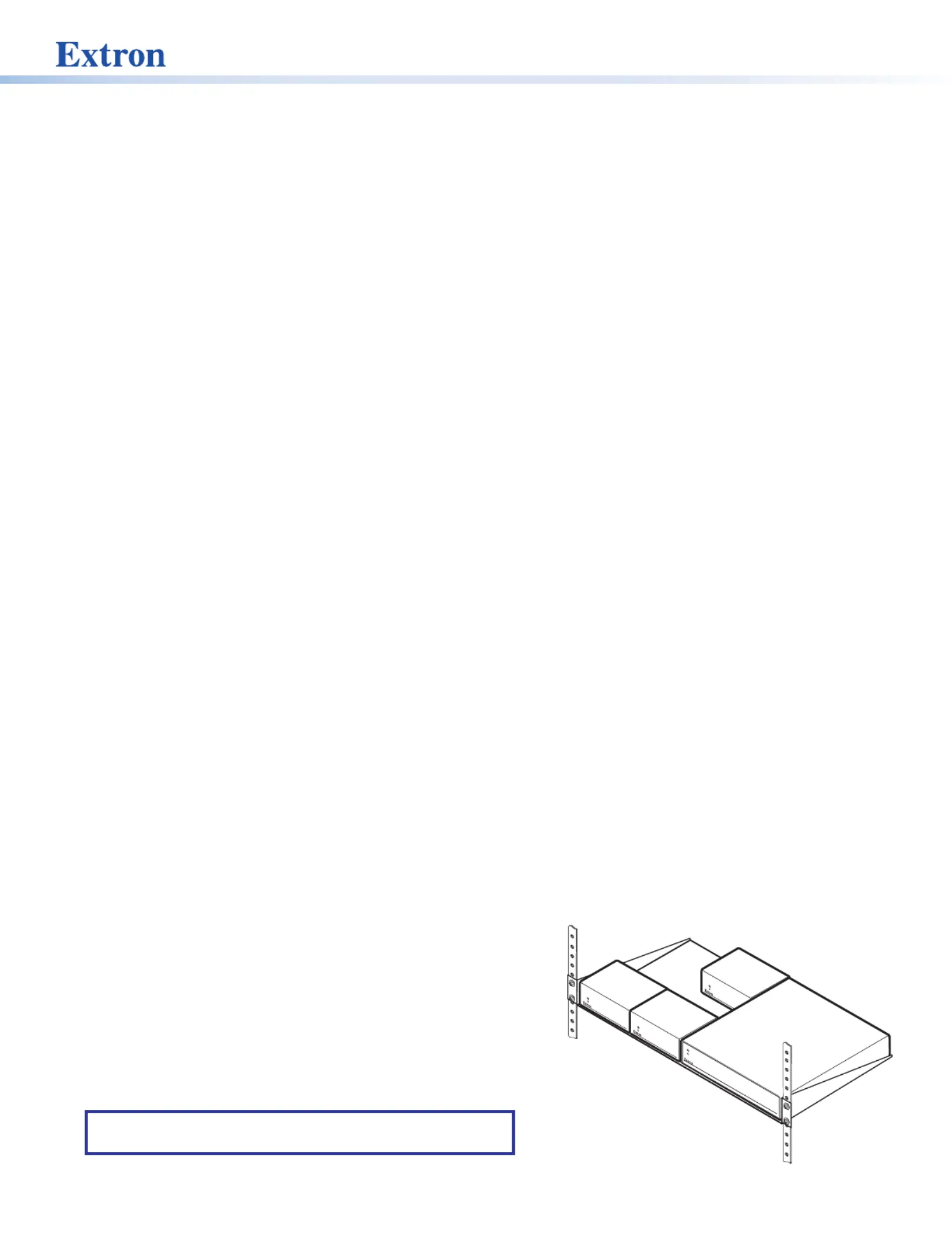
Rack mounting
For optional rack mounting, do not install the rubber feet. Mount the ASA on a 19” 1U rack shelf or a standard universal
1U rack shelf. On the standard rack shelf, the ASA mounts in one of four locations to the rear of the rack or in one of four
locations to the front of the rack.
1. Remove rubber feet if they were previously installed on the
bottom of the ASA.
2. Mount the ASA on the rack shelf, using two 4-40 x 3/16”
screws in opposite (diagonal) corners to secure the amplifier
to the shelf.
3. Install blank panels or other units on the rack shelf (see the
image on the right).
4. Attach the rack shelf to the rack using the supplied bolts.
NOTE: Most 1U rack-mountable Extron products can be
mounted on the standard shelf.
2
ASA 204 and ASA 304 • User Guide (Continued)
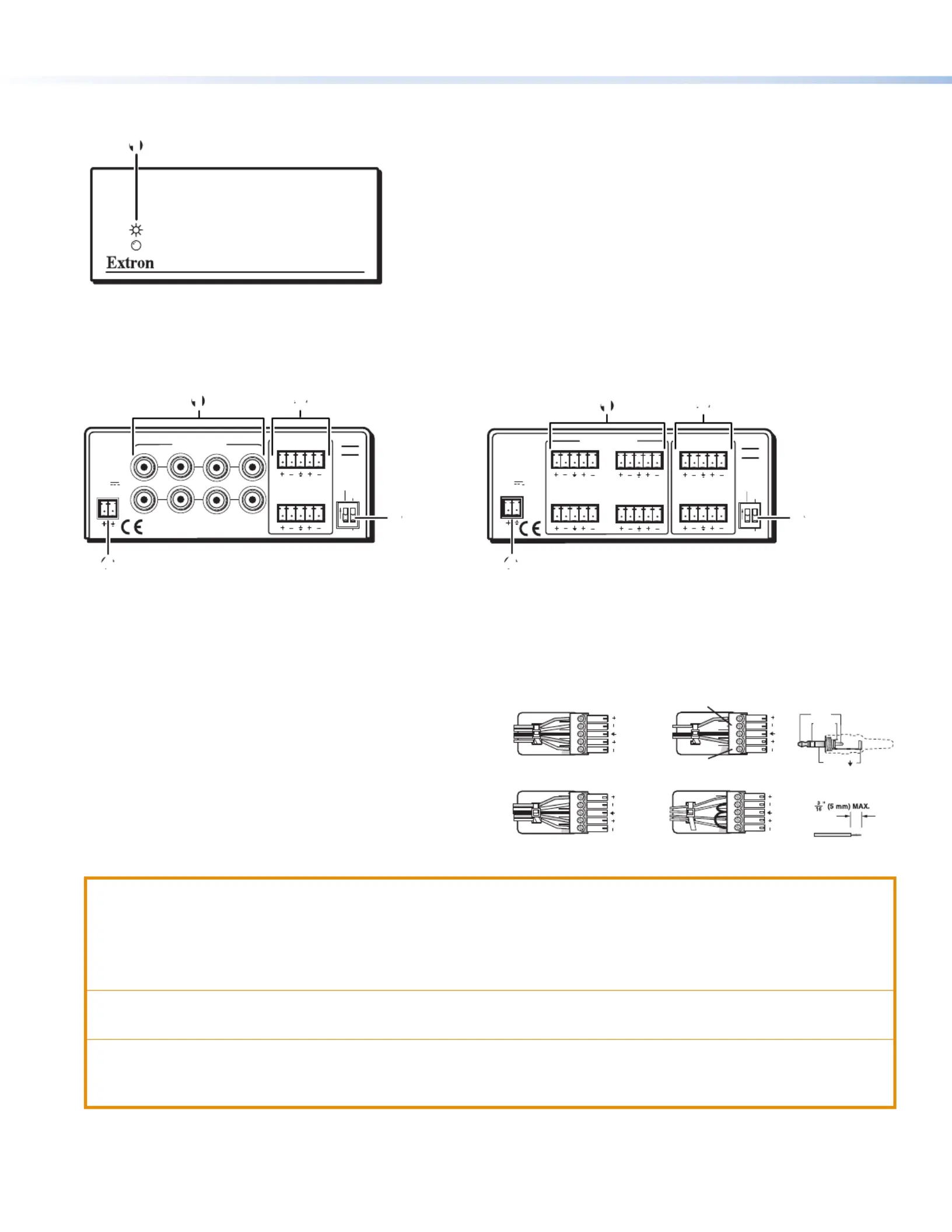
ASA 204/ASA 304 Front Panel Features
1
1
Power LED — Lights to indicate that the ASA is on.
Figure 1. ASA 204 and ASA 304 Front Panel
ASA 204/ASA 304 Rear Panel Features and Cabling
POWER
12V
.2A MAX
STEREO INPUTS
MONO OUTPUTS
BAL
UNBAL
ON
SPARE
3
1
4
2
43
21
L
QUAD AUDIO
SUMMING
AMPLIFIERS
R
ASA
204
L
L
R
R
1 2
3
4
STEREO INPUTS
BAL
UNBAL
ON
SPARE
MONO OUTPUTS
3
1
4
2
ASA
304
3
1
4
2
L R
L R
POWER
12V
.2A MAX
QUAD AUDIO
SUMMING
AMPLIFIERS
L R
L R
1 2
3
4
Figure 2. Figure 3. ASA 204 Rear Panel ASA 304 Rear Panel
1
Input Connector
3
Output gain DIP switch
2
Output Connector
4
Power connector
Balanced dio OutputAu
Tip
Ring
Tip
Ring
Slee
ves
Unbalanced dio OutputAu
Tip
No Ground Here
No Ground Here
Tip
Slee sve
L R
L R
Unbalanced dio InputBalanced dio Input AuAu
Tip
Ring
Tip
Ring
Slee
ves
Tip
Sleeve
Sleeve
Tip
L R
L R
Do not tin the wires!
RCA Connector
Slee ( )ve
Ring(R)
Tip(L)
Wire the audio input and output connectors as shown at
right. Use the supplied tie wrap to strap the audio cable
to the extended tail of the connector.
ATTENTION:
• Connect the sleeve to ground (Gnd). Connecting the sleeve to a negative (-) terminal will damage the audio
output circuits.
• Connectez le manchon à la borne de terre (Gnd). Connecter le manchon à une borne négative(-) endommagera
les circuits de la sortie audio.
• For unbalanced outputs, do not connect wires to the “-” poles (see the Extron Audio Wiring Card).
• Pour les sorties asymétriques, ne connectez pas de câbles aux pôles « - » (voir le Audio Wiring Card d’Extron).
• The length of exposed wires is . The ideal length is 3/16 inch (5 mm).critical
• La longueur des câbles exposés est lorsque l’on entreprend de les dénuder. La longueur idéale est primordiale
de 5mm (3/16inches).
3
3
Output gain DIP switch — Use this switch to set the audio output gain level.
Gain levels available via the switch vary depending on whether both inputs are receiving signals, and on the output
wiring, as shown in the table below.
Input Channel Output Output DIP Switch Settings
Left Right Wiring Unbalanced Balanced
signal signal balanced +9dB +3dB
signal —— balanced +3dB -3dB
—— signal balanced +3dB -3dB
signal signal unbalanced +3dB -3dB
signal —— unbalanced -3dB -9dB
—— signal unbalanced -3dB -9dB
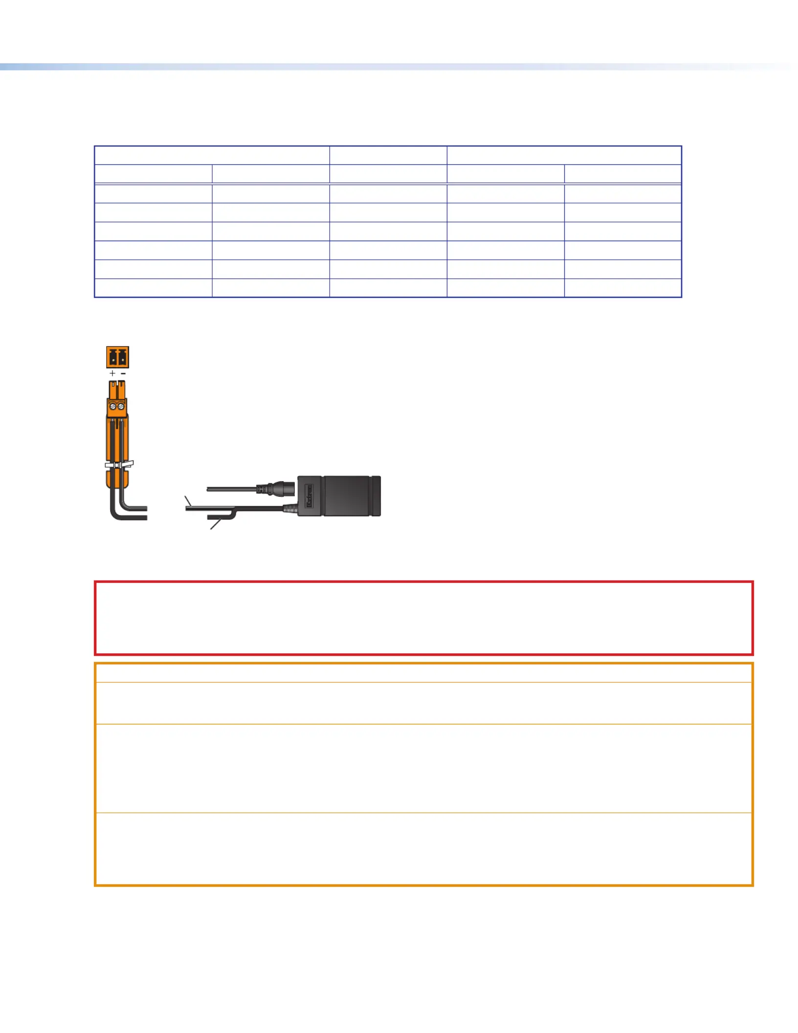
4
— An external 12 V power supply is included with the unit. Plug it into this 2-pole captive screw Power connector
connector. Wire the connector as shown below.
Rear Panel
Power Receptacle
DC Power Cord
Captive Screw
Connector
Ground
all devices.
External
Power Supply
(12 VDC, 0.5 A max.
)
– Return
+12 VDC input
Ridged
Smooth
Figure 4. Rear Panel 12 VDC Power Connector
CAUTION: The DC output cables must be kept separate from each other while the power supply is plugged in.
Remove power before wiring
AVERTISSEMENT : Les câbles de sortie CC doivent être séparés les uns des autres tant que la source
d’alimentation est branchée. Coupez l’alimentation avant d’effectuer les raccordements.
ATTENTION:
• Do not connect power to the amplifier until you have read the ATTENTION notifications.
• Ne branchez pas l’alimentation au l’amplificateur avant d’avoir lu les mises en garde « ATTENTION ».
• Always use a power supply supplied or specified by Extron. Use of an unauthorized power supply voids all
regulatory compliance certification and may cause damage to the supply and the end product.
• Utilisez toujours une source d’alimentation fournie ou recommandée par Extron. L’utilisation d’une source
d’alimentation non autorisée annule toute certification de conformité réglementaire et peut endommager la
source d’alimentation et l’unité.
• If not provided with a power supply, this product is intended to be supplied by a power source marked
“Class 2” or “LPS” and rated at 12VDC and a minimum of 0.5A.
• Si le produit n’est pas fourni avec une source d’alimentation, il doit être alimenté par une source
d’alimentation de classe 2 ou LPS, avec une tension nominale 12 Vcc, 0,5 A minimum.
Product Specifications
| Brand: | Extron |
| Category: | Receiver |
| Model: | ASA 304 |
Do you need help?
If you need help with Extron ASA 304, ask a question below and other users will answer you
Receiver Extron User Manuals

13 October 2024
13 October 2024
13 October 2024
13 October 2024
13 October 2024
13 October 2024
13 October 2024
13 October 2024
13 October 2024
13 October 2024
Receiver User Manuals
- Receiver Sony
- Receiver Bosch
- Receiver Brondi
- Receiver Jensen
- Receiver Hartke
- Receiver Goobay
- Receiver Avantree
- Receiver Cayin
- Receiver Axton
- Receiver Kogan
- Receiver Yamaha
- Receiver Lindy
- Receiver Pioneer
- Receiver NuPrime
- Receiver Ecler
- Receiver AudioControl
- Receiver Rotel
- Receiver Toa
- Receiver Marantz
- Receiver Pyle
- Receiver Wet Sounds
- Receiver JVC
- Receiver VMV
- Receiver S.M.S.L
- Receiver Kicker
- Receiver Auna
- Receiver OSD Audio
- Receiver Power Dynamics
- Receiver DataVideo
- Receiver Audizio
- Receiver Vonyx
- Receiver Bluesound
- Receiver Blackstar
- Receiver Cambridge
- Receiver MB Quart
- Receiver Aplic
- Receiver CSL
- Receiver NUVO
- Receiver Block
- Receiver Smart-AVI
- Receiver Advance
- Receiver Artsound
- Receiver Denon
- Receiver Yorkville
- Receiver Valcom
- Receiver Mosconi
- Receiver JBL
- Receiver Helix
- Receiver Soundstream
- Receiver Bellari
- Receiver Rolls
- Receiver Ground Zero
- Receiver Karma
- Receiver Glemm
- Receiver EA
- Receiver Match
- Receiver Renkforce
- Receiver Scansonic
- Receiver SPL
- Receiver Audiotec Fischer
- Receiver Crunch
- Receiver A-NeuVideo
- Receiver Classé
- Receiver FoneStar
- Receiver Monitor Audio
- Receiver Peavey
- Receiver Crown
- Receiver Fosi Audio
- Receiver Graupner
- Receiver Antelope Audio
- Receiver Vaddio
- Receiver ESX
- Receiver Omnitronic
- Receiver Russound
- Receiver MEE Audio
- Receiver GigaBlue
- Receiver Mx Onda
- Receiver Black Hydra
- Receiver Electro-Voice
- Receiver Boss
- Receiver JL Audio
- Receiver Shanling
- Receiver Atlas Sound
- Receiver Ashly
- Receiver Audiolab
- Receiver Memphis Audio
- Receiver AVM
- Receiver Primare
- Receiver PureLink
- Receiver Kramer
- Receiver ATen
- Receiver Blustream
- Receiver Yaesu
- Receiver Musical Fidelity
- Receiver RDL
- Receiver Dynacord
- Receiver Ferguson
- Receiver DAP Audio
- Receiver REL Acoustics
- Receiver Inovonics
- Receiver BZBGear
- Receiver Ram Audio
- Receiver Strong
- Receiver Phoenix Gold
- Receiver HiFi ROSE
- Receiver Intelix
- Receiver Comprehensive
- Receiver Deaf Bonce
- Receiver Fiio
- Receiver Lab Gruppen
- Receiver GlobalSat
- Receiver AVMATRIX
- Receiver Koda
- Receiver Technical Pro
- Receiver Marshall Electronics
- Receiver Naim
- Receiver Anthem
- Receiver Audison
- Receiver Hifonics
- Receiver Geemarc
- Receiver Loxjie
- Receiver Clare Controls
- Receiver Edwards Signaling
- Receiver Hegel
- Receiver August
- Receiver PTN-electronics
Latest Receiver User Manuals
27 October 2024
27 October 2024
27 October 2024
27 October 2024
27 October 2024
27 October 2024
27 October 2024
27 October 2024
27 October 2024
27 October 2024