Extron DVI DA Manual
Read below 📖 the manual in Italian for Extron DVI DA (5 pages) in the Receiver category. This guide has been helpful for 29 people and has been rated 4.5 stars on average by 2 users
Page 1/5
1
DVI DA2 and DVI DA 4 • User Guide
This guide describes the installation and operation of the Extron DVI DA2 and DVI DA4 Distribution Ampliers. Unless stated
otherwise, “distribution amplier” or “the unit” in this guide refer to both models.
About the DVI DA2 and DVI DA4
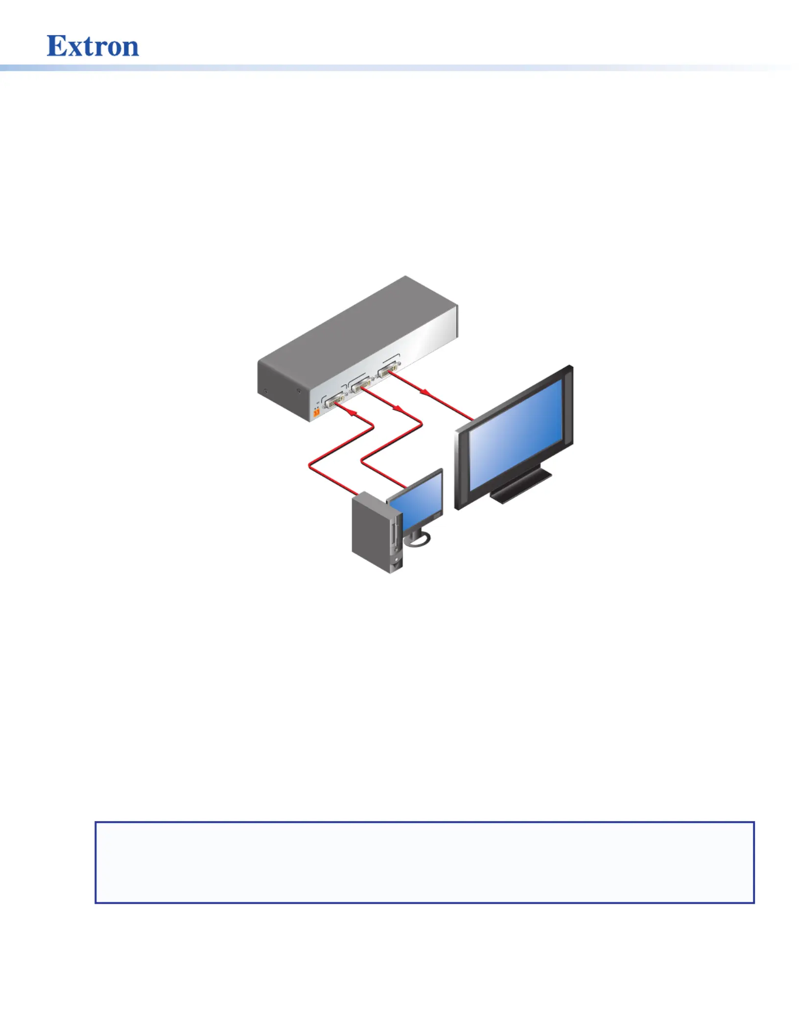
The Digital Visual Interface (DVI) Distribution Ampliers (DAs) have one input and either two (DVI DA2) or four (DVI DA4) outputs.
Output 1 for each model is for a local monitor and is used for Digital Display Channel (DDC) reference.
Both distribution ampliers accept one single link DVI-D input and drive two (DVI DA2) or four (DVI DA4) single link DVI-D output
signals.
12V
0.4A MAX
POWER
DVI-D INPUT DVI-D OUTPUT
1 2
DVI DA2
Ext
ron
DV
I 2DA
Dist
ribution A rmplie
PC
w/ DVI O tutpu
Loca orl Monit
Flat Panel Display
w/ DVI tInpu
Figure 1. DVI DA2 Application Diagram
DVI DA2 and DVI DA4 Features
• External power supply — The DVI DA2 and DVI DA4 are powered by an external 12VDC power supply (provided with the
units).
• DVI-D input — Both distribution ampliers accept one single link DVI-D input with a range of resolutions up to 1920 x 1200
or 1080p @ 60 Hz.
• Input equalization — Input Equalization (EQ) conditions the input signals to ensure the integrity of the signals delivered to
the output devices.
• DVI-D outputs — The units drive two (DVI DA2) or four (DVI DA4) single link DVI-D output signals.
• DDC routing to the local monitor — Output 1 is used as a DDC reference and is labeled “Local Monitor” for easy reference.
The video source uses the bidirectonal DDC to communicate with the local monitor, which allows the source to determine the
resolution and refresh rate of the signal that it sends.
NOTES:
• Since output 1 is used as the reference, all other display devices must be capable of handling resolutions equal to or
greater than that of the local monitor.
• The actual signal transmission distance can vary greatly and depends on signal resolution, cable type, cable quality,
graphics card, and the display used in the system.
• Versatile mounting options — Both units are 1U high, 3 inches (7.62 cm) deep, and 1/2rack (8.7 inches or 22.1 cm) wide,
allowing them to be conveniently mounted in a rack, mounted under a desk, or set on a tabletop.
2
Installation Overview
Both distribution ampliers can be placed on tabletops, or mounted under furniture or in racks by following these steps:
1. Turn off all electrical equipment. Make sure that the input sources, the DA and the output display(s) are all turned off and all
power sources and signal cables are disconnected.
2. Mount the unit (see page 5).Mounting
3. Connect the cables (see on page 3).DVI Connections
4. Plug in the (see page 3), then turn on the display devices and input devices.power supply
Front Panel Features
The front panels of the DVI DA2 and DVI DA4 are identical and shown in the illustration below
DVI DA SERIES
DVI DISTRIBUTION AMPLIFIER
11
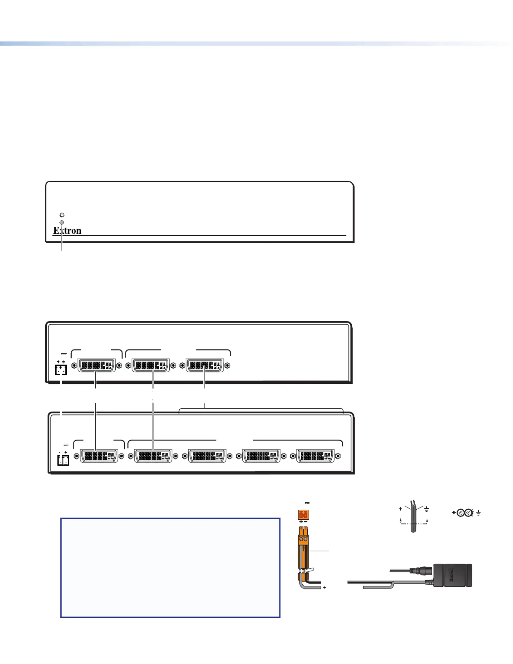
Figure 2. DVI DA2 and DVI DA4 Front Panel (both models are identical)
1
— On both the DVI DA2 and DVI DA4, the LED indicator lights when the unit is receiving power.LED indicator
Rear Panel Features
12V
0.4A MAX
POWER
DVI-D INPUT DVI-D OUTPUT
LOCAL MONITOR
1 2
DVI DA2
12V
0.4A MAX
POWER
DVI-D INPUT DVI-D OUTPUTS
LOCAL MONITOR
1 2 3 4
DVI DA4
11
2
23344
Figure 3. DVI DA2 (top) and DVI DA4 (bottom) Rear Panels
1
(see figure 3) — Connect the provided power supply Power input
DC Power
Input
POWER
12V
0.4A MA
X
Power Supply
Output Cord
SECTION A–
A
RidgesSmooth
A A
DC Power Cord
Captive Screw Connector
Ground
+12 VDC input
G
External Power Supply
(12 VDC, 0.5 A max.)
Ground all
Devices
to the 3.5 mm, captive screw power receptacle.
NOTES:
• The length of the exposed wires in the stripping process
is critical. The ideal length is 3/16 inch (5 mm).
• If the exposed section is , the exposed wires longer
may touch, causing a short circuit between them.
• If it is , the wires can be easily pulled out, shorter
even if tightly fastened by the captive screws.
• Do not tin the wires. Tinned wire does not hold its
shape and can become loose over time.
Figure 4. Power Connection

3
ATTENTION:
• If not provided with a power supply, this product is intended to be supplied by a UL Listed power source marked “Class
2” or “LPS” and rated output 12 VDC, 1.5 A minimum. Always use a power supply provided by or specied by Extron.
Use of an unauthorized power supply voids all regulatory compliance certication and may cause damage to the supply
and the end product.
• Si le produit n’est pas fourni avec une source d’alimentation, il doit être alimenté par une source d’alimentation certiée
UL de classe 2 ou LPS, avec une tension nominale 12 Vcc, 1,5 A minimum. Utilisez toujours une source d’alimentation
fournie ou recommandée par Extron. L’utilisation d’une source d’alimentation non autorisée annule toute certication de
conformité réglementaire, et peut endommager la source d’alimentation et l’unité.
• Unless otherwise stated, the AC/DC adapters are not suitable for use in air handling spaces or in wall cavities. The power
supply is to be located within the same vicinity as the Extron AV processing equipment in an ordinary location, Pollution
Degree 2, secured to the equipment rack within the dedicated closet, podium, or desk.
• Sauf mention contraire, les adaptateurs CA/CC ne conviennent pas à une utilisation dans les espaces d’aération ou dans
les cavités murales. La source d’alimentation doit être placée à proximité de l’équipement Extron dans un emplacement
ordinaire soumis à un degré de pollution de catégorie II, solidement xé au rack d’équipement d’une baie technique, d’un
pupitre, ou d’un bureau.
• The installation must always be in accordance with the applicable provisions of National Electrical Code ANSI/NFPA
70, article 725 and the Canadian Electrical Code part 1, section 16. The power supply shall not be permanently xed to
building structure or similar structure.
• Cette installation doit toujours être conforme aux dispositions applicables du Code américain de l’électricité (National
Electrical Code) ANSI/NFPA 70, article 725, et du Code canadien de l’électricité, partie 1, section 16. La source
d’alimentation ne devra pas être xée de façon permanente à la structure de bâtiment ou à d’autres structures similaires.
DVI Connections
2
(see on the previous page) — Connect the input signal to the female DVI connector. The DVI input Input connector figure 3
signal is equalized to ensure integrity.
3
— Connect up to two (DVI DA2) or four (DVI DA4) DVI-D outputs to display devices, using the female DVI Output connectors
connectors.
NOTE: The outputs are not HDCP compatible.
4
— Output 1 (Local Monitor) is used as a Hotplug Detect, a DDC clock, and a DDC data reference. Local Monitor connector
For the input device to provide a signal at the correct resolution and refresh rate, there must be a display device connected to
output1.
NOTE: Although the source device, local monitor, and remote display devices all connect to the distribution amplifiers
through DVI-I connectors, the DVI DA2 and DVI DA4 are compatible only with single-link DVI-D video signals.
To enable the units to accept sources providing HDMI signals or to provide signals to displays that accept HDMI signals,
use a HDMI to DVI adapter or cable, such as the Extron HDMIF-DVIDM female HDMI to male DVI-D adapter or the Extron
HDMIM-DVI-D M series of male HDMI to male DVI cables.
The input signal is one single link DVI-D with a resolution range up to 1920x1200 or 1080p@ 60 Hz.
Input EQ conditions input signals to ensure the integrity of the signals delivered to the output devices.
NOTES:
• The actual signal transmission distance can vary and depends on the signal resolution, cable quality, graphics card, and
display used in the system.
• To ensure proper operation, display devices connected to outputs 2 through 4 must be able to handle resolutions equal
or greater than that of the local monitor on output 1.
Product Specifications
| Brand: | Extron |
| Category: | Receiver |
| Model: | DVI DA |
Do you need help?
If you need help with Extron DVI DA, ask a question below and other users will answer you
Receiver Extron User Manuals

13 October 2024
13 October 2024
13 October 2024
13 October 2024
13 October 2024
13 October 2024
13 October 2024
13 October 2024
13 October 2024
13 October 2024
Receiver User Manuals
- Receiver Sony
- Receiver Bosch
- Receiver Brondi
- Receiver Jensen
- Receiver Hartke
- Receiver Goobay
- Receiver Avantree
- Receiver Cayin
- Receiver Axton
- Receiver Kogan
- Receiver Yamaha
- Receiver Lindy
- Receiver Pioneer
- Receiver NuPrime
- Receiver Ecler
- Receiver AudioControl
- Receiver Rotel
- Receiver Toa
- Receiver Marantz
- Receiver Pyle
- Receiver Wet Sounds
- Receiver JVC
- Receiver VMV
- Receiver S.M.S.L
- Receiver Kicker
- Receiver Auna
- Receiver OSD Audio
- Receiver Power Dynamics
- Receiver DataVideo
- Receiver Audizio
- Receiver Vonyx
- Receiver Bluesound
- Receiver Blackstar
- Receiver Cambridge
- Receiver MB Quart
- Receiver Aplic
- Receiver CSL
- Receiver NUVO
- Receiver Block
- Receiver Smart-AVI
- Receiver Advance
- Receiver Artsound
- Receiver Denon
- Receiver Yorkville
- Receiver Valcom
- Receiver Mosconi
- Receiver JBL
- Receiver Helix
- Receiver Soundstream
- Receiver Bellari
- Receiver Rolls
- Receiver Ground Zero
- Receiver Karma
- Receiver Glemm
- Receiver EA
- Receiver Match
- Receiver Renkforce
- Receiver Scansonic
- Receiver SPL
- Receiver Audiotec Fischer
- Receiver Crunch
- Receiver A-NeuVideo
- Receiver Classé
- Receiver FoneStar
- Receiver Monitor Audio
- Receiver Peavey
- Receiver Crown
- Receiver Fosi Audio
- Receiver Graupner
- Receiver Antelope Audio
- Receiver Vaddio
- Receiver ESX
- Receiver Omnitronic
- Receiver Russound
- Receiver MEE Audio
- Receiver GigaBlue
- Receiver Mx Onda
- Receiver Black Hydra
- Receiver Electro-Voice
- Receiver Boss
- Receiver JL Audio
- Receiver Shanling
- Receiver Atlas Sound
- Receiver Ashly
- Receiver Audiolab
- Receiver Memphis Audio
- Receiver AVM
- Receiver Primare
- Receiver PureLink
- Receiver Kramer
- Receiver ATen
- Receiver Blustream
- Receiver Yaesu
- Receiver Musical Fidelity
- Receiver RDL
- Receiver Dynacord
- Receiver Ferguson
- Receiver DAP Audio
- Receiver REL Acoustics
- Receiver Inovonics
- Receiver BZBGear
- Receiver Ram Audio
- Receiver Strong
- Receiver Phoenix Gold
- Receiver HiFi ROSE
- Receiver Intelix
- Receiver Comprehensive
- Receiver Deaf Bonce
- Receiver Fiio
- Receiver Lab Gruppen
- Receiver GlobalSat
- Receiver AVMATRIX
- Receiver Koda
- Receiver Technical Pro
- Receiver Marshall Electronics
- Receiver Naim
- Receiver Anthem
- Receiver Audison
- Receiver Hifonics
- Receiver Geemarc
- Receiver Loxjie
- Receiver Clare Controls
- Receiver Edwards Signaling
- Receiver Hegel
- Receiver August
- Receiver PTN-electronics
Latest Receiver User Manuals
27 October 2024
27 October 2024
27 October 2024
27 October 2024
27 October 2024
27 October 2024
27 October 2024
27 October 2024
27 October 2024
27 October 2024