Intellinet 509213 Manual
Intellinet
Not categorized
509213
Read below 📖 the manual in Italian for Intellinet 509213 (2 pages) in the Not categorized category. This guide has been helpful for 26 people and has been rated 4.5 stars on average by 2 users
Page 1/2
WASTE ELECTRICAL & ELECTRONIC EQUIPMENT
Disposal of Electric and Electronic Equipment (applicable in the E.U. and other countries with separate collection systems)
ENGLISH: This symbol on the product or its packaging means that this
product must not be treated as unsorted household waste. In
accordance with EU Directive 2012/19/EU on Waste Electrical and
Electronic Equipment (WEEE), this electrical product must be
disposed of in accordance with the user’s local regulations for
electrical or electronic waste. Please dispose of this product by
returning it to your local point of sale or recycling pickup point in your
municipality.
DEUTSCH: Dieses auf dem Produkt oder der Verpackung angebrachte Symbol
zeigt an, dass dieses Produkt nicht mit dem Hausmüll entsorgtwerden darf. In
Übereinstimmung mit der Richtlinie 2012/19/EU des Europäischen Parlaments
und des Rates über Elektro- und Elektronik-Altgeräte (WEEE) darf dieses
Elektrogerät nicht im normalen Hausmüll oder dem Gelben Sack entsorgt
werden. Wenn Sie dieses Produkt entsorgen möchten, bringen Sie es bitte zur
Verkaufsstelle zurück oder zum Recycling-Sammelpunkt Ihrer Gemeinde.
ESPAÑOL: Este símbolo en el producto o su embalaje indica que el producto
no debe tratarse como residuo doméstico. De conformidad con la Directiva
2012/19/EU de la UE sobre residuos de aparatos eléctricos y electrónicos
(RAEE), este producto eléctrico no puede desecharse se con el resto de
residuos no clasificados. Deshágase de este producto devolviéndolo a su
punto de venta o a un punto de recolección municipal para su reciclaje.
FRANÇAIS: Ce symbole sur Ie produit ou son emballage signifie que ce
produit ne doit pas être traité comme un déchet ménager. Conformément
à la Directive 2012/19/EU sur les déchets d’équipements électriques et
électroniques (DEEE), ce produit électrique ne doit en aucun cas être
mis au rebut sous forme de déchet municipal non trié. Veuillez vous
débarrasser de ce produit en Ie renvoyant à son point de vente ou au
point de ramassage local dans votre municipalité, à des fins de recyclage.
POLSKI: Jeśli na produkcie lub jego opakowaniu umieszczono ten symbol,
wówczas w czasie utylizacji nie wolno wyrzucać tego produktu wraz z
odpadami komunalnymi. Zgodnie z Dyrektywą Nr 2012/19/EU w sprawie
zużytego sprzętu elektrycznego i elektronicznego (WEEE), niniejszego
produktu elektrycznego nie wolno usuwać jako nie posortowanego
odpadu komunalnego. Prosimy o usuniecie niniejszego produktu
poprzez jego zwrot do punktu zakupu lub oddanie do miejscowego
komunalnego punktu zbiórki odpa dów przeznaczonych do recyklingu.
ITALIANO: Questo simbolo sui prodotto o sulla relativa confezione indica
che il prodotto non va trattato come un rifiuto domestico. In ottemperanza
alla Direttiva UE 2012/19/EU sui rifiuti di apparecchiature elettriche ed
elettroniche (RAEE), questa prodotto elettrico non deve essere smaltito come
rifiuto municipale misto. Si prega di smaltire il prodotto riportandolo al punto
vendita o al punto di raccolta municipale locale per un opportuno riciclaggio.
WARRANTY AT: | GARANTIE AUF: | GARANTÍA EN: | GARANTIE À : | GWARANC JA NA: | GARANZIA A: | GARANCIJA NA:
intellinet-network.com
EN MÉXICO: Póliza de Garantía Intellinet Network Solutions — Datos del importador y responsable ante el consumidor • IC Intracom México, S.A.P.I.
de C.V. • Av. Interceptor Poniente # 73, Col. Parque Industrial La Joya, Cuautitlán Izcalli, Estado de México, C.P. 54730, México. • Tel. (55)1500-4500
La presente garantía cubre los siguientes productos contra cualquier defecto de fabricación en sus materiales y mano de obra.
A Garantizamos los productos de limpieza, aire comprimido y consumibles, por 60 dias a partir de la fecha de entrega, o por
el tiempo en que se agote totalmente su contenido por su propia función de uso, lo que suceda primero.
B Garantizamos los productos con partes móviles por 3 años.
C Garantizamos los demás productos por 5 años (productos sin partes móviles), bajo las siguientes condiciones:
1 Todos los productos a que se refiere esta garantía, ampara su cambio físico, sin ningún cargo para el consumidor.
2 El comercializador no tiene talleres de servicio, debido a que los productos que se garantizan no
cuentan con reparaciones, ni refacciones, p1-ya que su garantía es de cambio físico.
3 La garantía cubre exclusivamente aquellas partes, equipos o sub-ensambles que hayan sido instaladas de fábrica y no incluye
en ningún caso el equipo adicional o cualesquiera que hayan sido adicionados al mismo por el usuario o distribuidor.
Para hacer efectiva esta garantía bastará con presentar el producto al distribuidor en el domicilio donde fue adquirido o en el domicilio de
IC Intracom México, S.A.P.I. de C.V., junto con los accesorios contenidos en su empaque, acompañado de su póliza debidamente llenada
y sellada por la casa vendedora (indispensable el sello y fecha de compra) donde lo adquirió, o bien, la factura o ticket de compra original
donde se mencione claramente el modelo, número de serie (cuando aplique) y fecha de adquisición. Esta garantía no es válida en los
siguientes casos: Si el producto se hubiese utilizado en condiciones distintas a las normales; si el producto no p1-ha sido operado conforme
a los instructivos de uso; o si el producto p1-ha sido alterado o tratado de ser reparado por el consumidor o terceras personas.
REGULATORY STATEMENTS
Class A
This equipment has been tested and found to comply with the limits for a Class A digital device, pursuant to Part 15 of the Federal Communications Commission
(FCC) Rules. These limits are designed to provide reasonable protection against harmful interference when the equipment is operated in a commercial
environment. This equipment generates, uses and can radiate radio frequency energy, and if not installed and used in accordance with the instruction manual
may cause harmful interference to radio communications. Operation of this equipment in a residential area is likely to cause harmful interference, in which
case the user will be required to correct the interference at his own expense. Any changes or modifications made to this equipment without the approval of
the manuafacturer could result in the product not meeting the Class A limits, in which case the FCC could void the user’s authority to operate the equipment.
CE
ENGLISH : This device complies with the requirements of CE 2014/30/EU and/or 2014/35/EU. The Declaration of Conformity for is available at:
DEUTSCH : Dieses Gerät enspricht der CE 2014/30/EU und / oder 2014/35/EU. Die Konformitätserklärung für dieses Produkt finden Sie unter:
ESPAÑOL : Este dispositivo cumpl e con los requer imientos de CE 2014/30/EU y / o 2014/35/EU. La d eclaración d e conformidad e sta disponib le en:
FRANÇAIS : Cet appareil satisfait aux exigences de CE 2014/30/EU et/ou 2014/35/EU. La Déclaration de Conformité est disponible à :
POLSKI : Urządzenie spełnia wymagania CE 2014/30/EU I / lub 2014/35/EU. Deklaracja zgodności dostępna jest na stronie internetowej producenta:
ITALIANO : Questo dispositivo è conforme alla CE 2014/30/EU e / o 2014/35/EU. La dichiarazione di conformità è disponibile al:
support.intellinet-network.com/barcode/509213
Important: Read before use. • Importante: Leer antes de usar.
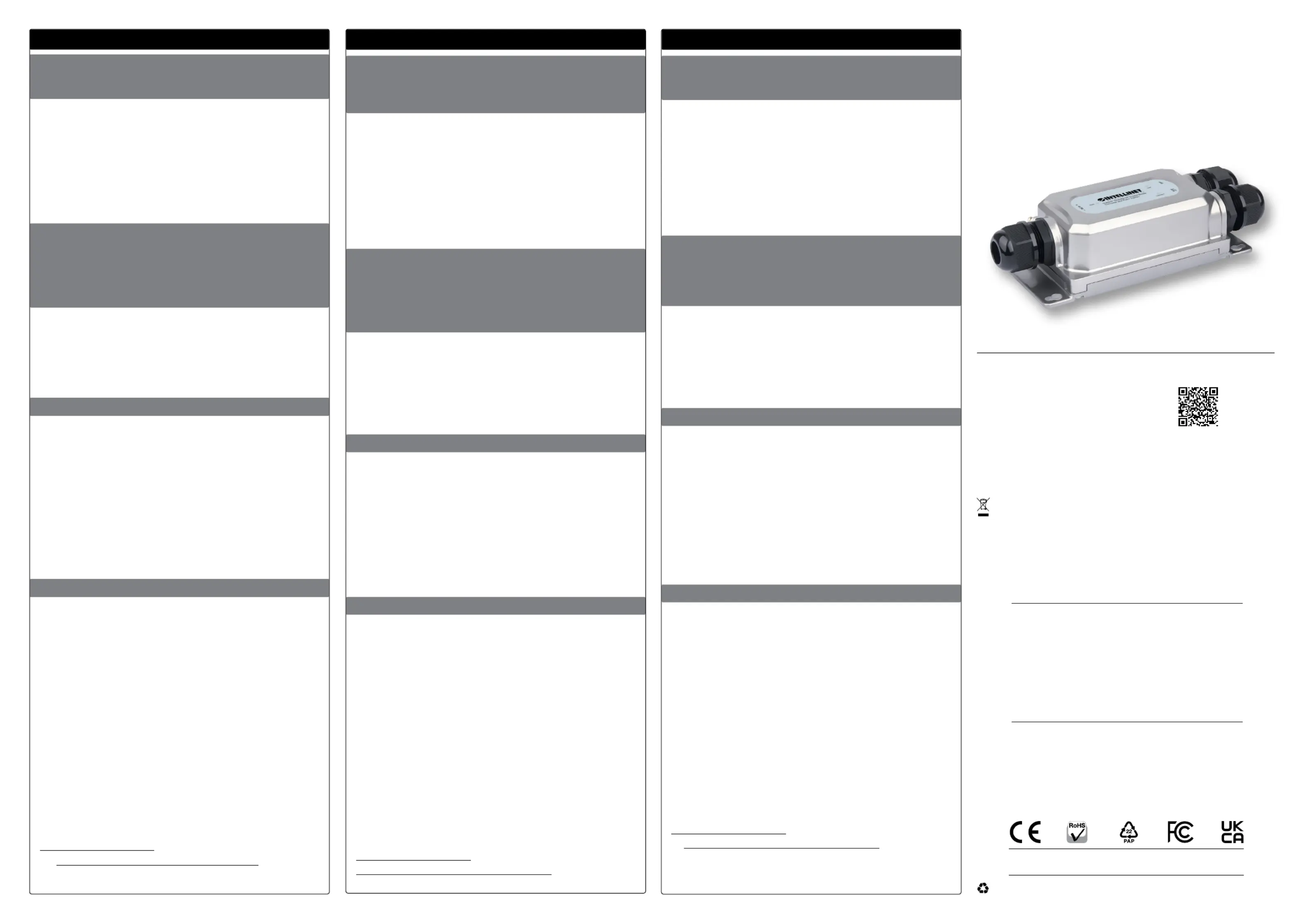
Outdoor Vandalproof
Gigabit Media
Converter and PoE+
Injector Instructions
Model 509213 (IMCI-SFPG-OD30W)
INT_509213_QIG_1123_REV_5.11
All trademarks and trade names are the property of their respective owners. © IC Intracom.
All rights reserved. Intellinet Network Solutions is a trademark of IC Intracom, registered in the U.S. and other countries.
Printed on recycled paper.
FRANÇAIS
Raccordements: Suivez ces étapes pour vous
assurer de raccordements étanches pour tous
les câbles qui conduisent à l’appareil.
1 Faites passer le câble à travers le corps (Body) et
l’écrou (Nut). Reliez le raccord (Insert) entre les deux.
2 Placez la fiche du câble dans la prise/le port.
3 Serrez bien le corps à l’appareil (Utilisez la clé incluse).
4 Insérer dans le corps en poussant.
5 Serrez bien l’écrou au corps fileté.
Branchements électriques — AVERTISSEMENT:
Assurez-vous que l’alimentation est intégralement
éteinte/déconnectée avant de commencer !
Vérifiez que votre adaptateur de puissance
est conforme aux spécifications de l’appareil
(courant continu: 24,0 à 56,0V ; max. 2 A).
6 Insérez les fils d’alimentation nus dans les fentes
prévues à cet effet de la fiche du bornier (fil
positif dans l’emplacement positif ; fil négatif dans
l’emplacement négatif). Serrez les vis appropriées
pour fixer les fils. Insérez la fiche dans la prise.
Connexions de données
7 Connectez un câble en fibre (ø 1,7 mm-3 mm)
depuis un périphérique réseau au port SFP.
8 Connectez le câble Ethernet de catégorie 5e/6/6a
a d’un dispositif PoE au port «RJ45 (PoE 30W)».
9 Raccordez la borne de terre à un objet mis
à la terre afin de protéger l’équipement
contre les surtensions externes.
10 Vérifiez si tous les raccordements sont
bien branchés et allumez le courant.
Remarques
• : PWR (Vert – l’unité est alimentée); LNK LEDs
(Vert – la liaison est établie avec succès à
1000Mbps); LNK/ACT (Vert – la liaison est établie
avec succès à 10/100/1000Mbps; Clignotant –
Transmission de données et/ou d'énergie).
• Montage mural: Commencez par placer
les vis (avec une tête de 5,5 à 6,5mm) dans
le mur à la distance indiquée. Suspendez
ensuite l’unité sur les vis et faites-la glisser
jusqu’à ce que’elle tienne bien en place.
• Prend en charge tous les dispositifs PoE compatibles
IEEE 802.3af/at : point d’accès LAN sans fil et ponts,
téléphones VoIP (Voice over Internet Protocol
— voix sur IP) et caméras de surveillance IP.
Vous trouvez les spécifications sur
intellinet-network.com. Enregistrez votre produit
sur register.intellinet-network.com/r/509213 ou
scannez le code QR figurant sur la couverture.
POLSKI
Połączenia kablowe: postępuj zgodnie z
poniższymi ogólnymi krokami, aby wykonać
wodoszczelne połączenia wszystkich
kabli podłączanych do urządzenia.
1 Przełóż przewód przez nakrętkę (Nut) i korpus
(Body). Zamocuj wkładkę (Insert) pomiędzy nimi.
2 Włóż wtyczkę kabla do przyłącza/gniazda.
3 Dokręć korpus do urządzenia (Należy użyć
klucza załączonego w zestawie).
4 Wepchnij wkład do korpusu.
5 Dokręć nakrętkę do korpusu.
Połączenia zasilania — OSTRZEŻENIE:Przed
rozpoczęciem działania należy upewnić się, że
odłączono lub wyłączono całe zasilanie! Make sure your
power adapter complies with the speciUpewnij się,
że zasilacz sieciowy jest zgodny ze specyfikacją tego
urządzenia (wejście DC: 24,0 - 56,0 V DC, maks. 2 A).
6 Włóż nieizolowane przewody zasilające w
odpowiednie gniazda na wtyczce bloku zacisków
(żyła o polaryzacji dodatniej w szczelinie dodatniej,
żyła o polaryzacji ujemnej w szczelinie ujemnej). W
celu zabezpieczenia przewodów należy dokręcić
odpowiednie śruby. Włóż wtyczkę do gniazdka.
Połączenia do transmisji danych
7 Podłącz kabel światłowodowy (ø1,7 mm-3 mm)
z urządzenia sieciowego do portu SFP.
8 Podłącz kabel Ethernet Cat5e/6/6a z
urządzenia PoE do portu RJ45 (PoE 30W).
9 Podłącz zacisk uziemiający do uziemienia, aby chronić
sprzęt przed zewnętrznymi przepięciami elektrycznymi.
10 Upewnij się, że wszystkie połączenia
są bezpieczne i włącz zasilanie.
Uwagi
• : PWR (Zielony – urządzenie jest podłączone LEDs
do zasilania); LNK (Zielony – połączenie zostało
pomyślnie nawiązane z prędkością 1000 Mb/s);
LNK/ACT (Zielony – połączenie zostało pomyślnie
nawiązane z prędkością 10/100/1000Mbps;
Migająca – przesyłanie danych i/lub zasilania.).
• : najpierw wkręć śruby (zalecana Montaż ścienny
średnica nakrętki 5,5 - 6,5 mm) w ścianie z
zachowaniem odpowiednich odległości. Następnie
zawieś urządzenie na śrubach i wsuń je na swoje
miejsce w taki sposób, aby było stabilne.
• Urządzenie zgodne ze standardem IEEE
802.3af/at PoE obsługujące bezprzewodowe
access pointy i bridge, telefony VoIP.
Specyfikacja techniczna dostępna jest na stronie
intellinet-network.com. Zarejestruj produkt na
register.intellinet-network.com/r/509213 lub
zeskanuj znajdujący się na pokrywie kod QR.
ITALIANO
Collegamenti dei cavi: seguire questi passaggi
generali per effettuare collegamenti impermeabili
su tutti i cavi che si collegano all’unità.
1 Inserire il cavo attraverso il dado (Nut) e il corpo
(Body). Agganciare l’inserto (Insert) tra i due.
2 Installare la spina del cavo nella porta/presa.
3 Serrare il corpo all’unità (Utilizzare
la chiave in dotazione).
4 Spingere l’inserto nel corpo.
5 Serrare il dado al corpo.
Connessioni di alimentazione — AVVERTIMENTO:
Prima di iniziare, assicurarsi che l’alimentazione sia
staccata/disattivata! Assicurarsi che l’alimentatore
sia conforme alle specifiche di questa unità
(ingresso CC: 24,0 - 56,0 V CC, 2 A max.).
6 Inserire i cavi di alimentazione scoperti negli
slot appropriati sulla presa della morsettiera
(il cavo positivo nell’alloggiamento del
positivo; il cavo negativo nell’alloggiamento
del negativo). Serrare le viti appropriate per
fissare i cavi. Installare la spina nella presa.
Connessioni dati
7 Collegare un cavo in fibra (ø1,7mm – 3mm)
da un dispositivo di rete alla porta SFP.
8 Collegare il cavo Ethernet Cat5e/6/6a da un
dispositivo PoE alla porta RJ45 (PoE 30W).
9 Collegare il terminale di messa a terra a un oggetto
di messa a terra per proteggere l’apparecchiatura
da sovratensioni elettriche esterne.
10 Assicurarsi che tutte le connessioni siano
sicure e attivare l’alimentazione.
Appunti
• : PWR (Verde – l’unità è alimentata); LNK (Verde LEDs
– È stato correttamente stabilito il collegamento a
1000Mbps); LNK/ACT (Verde – È stato correttamente
stabilito il collegamento a 10/100/1000Mbps;
Lampeggiante – Trasmissione di dati e/o alimentazione).
• : per prima cosa, installare Montaggio a parete
le viti (diametro del tappo a vite consigliato di
5,5 – 6,5 mm) nella parete a distanze appropriate.
Quindi, appendere l’unità alle viti e farla scorrere
in posizione finché non è correttamente fissata.
• Supporta tutte le periferiche conformi IEEE 802.3af/at:
punti di accesso Wireless LAN e bridge, telefoni VoIP
(Voice over Internet Protocol), camere di sorveglianza IP.
Per ulteriori specifiche, visita il sito
intellinet-network.com. Registra il tuo prodotto
su register.intellinet-network.com/r/509213 o
scansiona il codice QR presente sulla copertina.
or go to: register.intellinet-network.com/r/509213
Scan to
register your
product warranty
For additional benets:
North & South America
IC Intracom Americas
550 Commerce Blvd.
Oldsmar, FL 34677, USA
Asia & Africa
IC Intracom Asia
4-F, No. 77, Sec. 1, Xintai 5th Rd.
Xizhi Dist., New Taipei City 221,
Taiwan
Europe
IC Intracom Europe
Löhbacher Str. 7
D-58553 Halver, Germany

ENGLISH
Cable Connections: Follow these general
steps to make waterproof connections
on all cables that connect to the unit.
1 Insert cable through Nut and Body.
Attach Insert between them.
2 Install cable plug into port/outlet.
3 Tighten Body to unit (Use the included Wrench).
4 Push Insert into Body.
5 Tighten Nut to Body.
Power Connections — WARNING: Ensure
all power is off/disconnected before
beginning! Make sure your power adapter
complies with the specifications of this unit
(DC input: 24.0 - 56.0 V DC, 2 A max.).
6 Insert bare power-supply wires into appropriate
slots on terminal block plug (positive
wire into positive slot; negative wire into
negative slot). Tighten appropriate screws
to secure wires. Install plug into outlet.
Data Connections
7 Connect a fiber cable (ø 1.7mm-3mm) from
a network device to the SFP port.
8 Connect Cat5e/6/6a Ethernet cable from a
PoE device to the RJ45 (PoE 30W) port.
9 Wire the grounding terminal to an earth-
grounding object to protect equipment
from external electrical surges.
10 Ensure all connections are secure and apply power.
Notes
• : PWR (green – unit has power); LNK LEDs
(Green – the link is successfully established
at 1000Mbps); LNK/ACT (Green – the link is
successfully established at 10/100/1000Mbps;
Flashing – transmitting data and/or power).
• : First, install screws (5.5 – 6.5 mm Wall mounting
screw head diameter recommended) into wall
at appropriate distances. Then, hang the unit on
the screws and slide it into place so it is secure.
• Supports all IEEE 802.3af/at-compliant PoE
devices (wireless LAN access points and bridges,
VoIP telephones, IP surveillance cameras).
For specifications, please visit visit
intellinet-network.com. Register your product
at register.intellinet-network.com/r/509213
or scan the QR code on the cover sheet.
DEUTSCH
Kabelanschlüsse: Befolgen Sie diese einfachen
Schritte, um eine wasserdichte Verbindung aller Kabel
herzustellen, die mit dem Gerät verbunden sind.
1 Führen Sie das Kabel durch die Mutter
(Nut) und das Gehäuse (Body). Befestigen
Sie den Einsatz (Insert) dazwischen.
2 Bringen Sie den Kabelstecker am
Anschluss / Ausgang an.
3 Schrauben Sie das Gehäuse am Gerät fest (Benutzen
Sie den mitgelieferten Schraubenschlüssel).
4 Schieben Sie den Einsatz in das Gehäuse.
5 Ziehen Sie die Mutter am Gehäuse fest.
Stromanschlüsse — WARNUNG: Vergewissern
Sie sich, dass die Stromversorgung vor Beginn
abgeschaltet/getrennt ist! Vergewissern Sie sich,
dass Ihr Netzteil den Anforderungen dieses Geräts
entspricht (DC-Eingang: 24,0 - 56,0 V DC, 2 A max.).
6 Stecken Sie die freien Stromversorgungsdrähte in die
entsprechenden Anschlüsse des Klemmleistensteckers
(Pluskabel in den Plus-Steckplatz; Minuskabel
in den Minus-Steckplatz). Ziehen Sie die
entsprechenden Schrauben an, um die Kabel zu
fixieren. Stecken Sie den Stecker in die Steckdose.
Datenverbindungen
7 Schließen Sie ein Netzwerkgerät mithilfe eines
Glasfaserkabels (ø1,7 mm-3 mm) an den SFP-Port an.
8 Schließen Sie ein Cat5e/6/6a-Ethernet-Kabel von
einem PoE-Gerät an den RJ45-(PoE 30W)-Port an.
9 Verbinden Sie die Erdungsklemme mit
einem geerdeten Objekt, um das Gerät
vor Überspannung zu schützen.
10 Vergewissern Sie sich, dass alle Anschlüsse
gesichert sind und schalten Sie das Gerät ein.
Hinweise
• : PWR (Grün – Gerät wird mit Strom versorgt); LNK LEDs
(Grün – die Verbindung wird bei 1000 Mbps erfolgreich
hergestellt.); LNK/ACT (Grün – die Verbindung wird
bei 10/100/1000Mbps Mbps erfolgreich hergestellt;
Blinkend – Übertragung von Daten und/oder Strom).
• Wandmontage: Bringen Sie zunächst Schrauben (5,5
- 6,5 mm Schraubenkopfdurchmesser empfohlen)
in entsprechenden Abständen an der Wand an.
Hängen Sie anschließend das Gerät an den Schrauben
ein und platzieren Sie es so, dass es sicher hält.
• Unterstützt alle IEEE 802.3af/at-konformen PoE-Geräte
(z. B. Access Points, VoIP-Telefone und IP-Kameras).
Die Spezifikationen finden Sie auf
intellinet-network.com. Registrieren Sie Ihr Produkt
auf register.intellinet-network.com/r/509213 oder
scannen Sie den QR-Code auf dem Deckblatt.
ESPAÑOL
Conexiones por cable: siga estos pasos de manera
completa para realizar las conexiones a prueba de
agua en aquellos cables que se enchufan al equipo.
1 Inserte el cable a través de la tuerca (Nut)
y el orificio roscado (Body). Coloque la
pieza insertada (Insert) entre ellos.
2 Instale el enchufe del cable en el puerto/tomacorriente.
3 Asegure el orificio roscado a la unidad
(Utilice la llave inglesa que se incluye).
4 Presione bien la pieza insertada al orificio.
5 Ajuste bien la tuerca al orificio roscado.
Conexiones eléctricas — ADVERTENCIA: asegúrese
de que toda fuente de energía esté apagada/
desconectada antes de comenzar. Compruebe
que el adaptador de corriente cumpla con las
especificaciones de este ensamblaje (conector
de entrada CC: 24,0 - 56,0 V CC, 2 A máx.).
6 Inserte los cables o alambres pelados de corriente
eléctrica en las ranuras correspondientes del enchufe
del bloque de terminales (cable positivo en orificio
positivo, cable negativo en orificio negativo). Apriete
los tornillos correspondientes para asegurar los
cables. Instale el enchufe en el tomacorriente.
Conexiones de datos
7 Conecte el cable de fibra óptica (diámetro: 1,7 mm-3
mm) desde un dispositivo de red al puerto SFP.
8 Conecte el cable Ethernet Cat5e/6/6a desde un
dispositivo PoE al puerto de RJ45 (PoE 30W).
9 Ensamble el terminal de tierra a un objeto
de puesta a tierra para proteger al equipo
de oscilaciones eléctricas externas.
10 Verifique que todas las conexiones
estén seguras y activadas.
Notas
• : PWR (Verde – el equipo se encuentra LEDs
encendido); LNK (Verde – el enlace se establece
con éxito a 1000 Mbps); LNK/ACT (Verde – El
enlace se establece con éxito a 10/100/1000Mbps;
Parpadeo – Transmisión de datos o potencia).
• Montaje en la pared: primero, coloque los tornillos
(se recomienda un diámetro de tapa roscada de
5,5 a 6,5 mm) en la pared a distancias indicadas.
Posteriormente, enganche el dispositivo en los tornillos
y deslícelo en su lugar hasta que esté seguro.
• Soporta todos los dispositivos compatibles con IEEE
802.3af/at (access points y puentes, télefonos VoIP
[Protocolo de Voz sobre Internet], cámaras IP).
Para más especificaciones, visite
intellinet-network.com. Registre el producto
en register.intellinet-network.com/r/509213
o escanee el código QR en la cubierta.
1
Nut Insert Body
2
3
4
5
9
6
7
8
Product Specifications
| Brand: | Intellinet |
| Category: | Not categorized |
| Model: | 509213 |
Do you need help?
If you need help with Intellinet 509213, ask a question below and other users will answer you
Not categorized Intellinet User Manuals

15 October 2024
15 October 2024
15 October 2024
14 October 2024
14 October 2024
14 October 2024
14 October 2024
14 October 2024
14 October 2024
14 October 2024
Not categorized User Manuals
- Not categorized Candy
- Not categorized Sony
- Not categorized Electrolux
- Not categorized Samsung
- Not categorized Xiaomi
- Not categorized Casio
- Not categorized LG
- Not categorized Bosch
- Not categorized AEG
- Not categorized IKEA
- Not categorized Huawei
- Not categorized Braun
- Not categorized Brondi
- Not categorized HP
- Not categorized Philips
- Not categorized Panasonic
- Not categorized Bauknecht
- Not categorized BEKO
- Not categorized Delonghi
- Not categorized Daewoo
- Not categorized DeWalt
- Not categorized Epson
- Not categorized Etna
- Not categorized Teka
- Not categorized Apc
- Not categorized Balay
- Not categorized Siemens
- Not categorized Hama
- Not categorized Petsafe
- Not categorized Vorago
- Not categorized Neewer
- Not categorized Danby
- Not categorized Bartscher
- Not categorized Hartke
- Not categorized Bertazzoni
- Not categorized Gigabyte
- Not categorized Smeg
- Not categorized Hisense
- Not categorized Gree
- Not categorized Hoover
- Not categorized EBERLE
- Not categorized Hazet
- Not categorized Fluke
- Not categorized Goobay
- Not categorized Topeak
- Not categorized Antari
- Not categorized Thermex
- Not categorized TCL
- Not categorized Russell Hobbs
- Not categorized Panduit
- Not categorized IFM
- Not categorized Avantree
- Not categorized Royal Catering
- Not categorized Hotpoint
- Not categorized Whirlpool
- Not categorized Schwaiger
- Not categorized Nabo
- Not categorized Arendo
- Not categorized Megger
- Not categorized Balam Rush
- Not categorized Noxon
- Not categorized Sanus
- Not categorized Adidas
- Not categorized Domo
- Not categorized Cayin
- Not categorized Reflexion
- Not categorized TP Link
- Not categorized Inventum
- Not categorized Totolink
- Not categorized Shokz
- Not categorized Gamma
- Not categorized Artusi
- Not categorized Medel
- Not categorized Meris
- Not categorized D-Link
- Not categorized Navitel
- Not categorized Meridian
- Not categorized AeroCool
- Not categorized Kugoo
- Not categorized Rikon
- Not categorized Neff
- Not categorized Garmin
- Not categorized Razer
- Not categorized Teufel
- Not categorized Enermax
- Not categorized Noveen
- Not categorized StarTech.com
- Not categorized Origin Storage
- Not categorized Outwell
- Not categorized Best
- Not categorized Stihl
- Not categorized Kostal
- Not categorized ZOTAC
- Not categorized Comfee
- Not categorized Imarflex
- Not categorized Edgestar
- Not categorized Audient
- Not categorized Kogan
- Not categorized Solis
- Not categorized DJI
- Not categorized Snom
- Not categorized McIntosh
- Not categorized One For All
- Not categorized Caple
- Not categorized SereneLife
- Not categorized Roesle
- Not categorized APSystems
- Not categorized GoGEN
- Not categorized Festo
- Not categorized Create
- Not categorized Furrion
- Not categorized Oreg
- Not categorized Glorious
- Not categorized Pro-Ject
- Not categorized Yamaha
- Not categorized CaviLock
- Not categorized OOONO
- Not categorized Venom
- Not categorized Kichler
- Not categorized SMART Technologies
- Not categorized Neo
- Not categorized Newstar
- Not categorized Legrand
- Not categorized Integral LED
- Not categorized Goodram
- Not categorized Goldtouch
- Not categorized Lutec
- Not categorized Vello
- Not categorized Asus
- Not categorized Cudy
- Not categorized Hayter
- Not categorized BlueBuilt
- Not categorized Eufy
- Not categorized Gys
- Not categorized Conair
- Not categorized Turmix
- Not categorized Franke
- Not categorized Husqvarna
- Not categorized Sauber
- Not categorized Shimano
- Not categorized Axis
- Not categorized Tamron
- Not categorized Liebherr
- Not categorized Carson
- Not categorized Gourmetmaxx
- Not categorized Truelife
- Not categorized Busch-Jaeger
- Not categorized ETA
- Not categorized Voltcraft
- Not categorized Axor
- Not categorized Karran
- Not categorized Elkay
- Not categorized Varaluz
- Not categorized Extron
- Not categorized Lindy
- Not categorized Aputure
- Not categorized Netgear
- Not categorized Honor
- Not categorized XP-PEN
- Not categorized Danfoss
- Not categorized Riccar
- Not categorized Orbegozo
- Not categorized Media-tech
- Not categorized Kuppersbusch
- Not categorized Mebby
- Not categorized Pioneer
- Not categorized TONI&GUY
- Not categorized Summit
- Not categorized Accucold
- Not categorized EarFun
- Not categorized Toolcraft
- Not categorized Gram
- Not categorized Lorex
- Not categorized Catit
- Not categorized NuPrime
- Not categorized Ecler
- Not categorized Roccat
- Not categorized AudioControl
- Not categorized Elsner
- Not categorized Kask
- Not categorized Digitus
- Not categorized Cabasse
- Not categorized Koenic
- Not categorized Haier
- Not categorized Beaphar
- Not categorized Sure Petcare
- Not categorized Livall
- Not categorized Monogram
- Not categorized Sortimo
- Not categorized Unicol
- Not categorized Audio-Technica
- Not categorized Lian Li
- Not categorized JLab
- Not categorized Toa
- Not categorized Marantz
- Not categorized Knog
- Not categorized Rega
- Not categorized Vox
- Not categorized Mars Gaming
- Not categorized Kerbl
- Not categorized Metra
- Not categorized Pyle
- Not categorized Sencor
- Not categorized Hobby
- Not categorized Lenovo
- Not categorized Noctua
- Not categorized Klein Tools
- Not categorized LevelOne
- Not categorized Shure
- Not categorized Michael Todd Beauty
- Not categorized GRAUGEAR
- Not categorized Trixie
- Not categorized Schneider
- Not categorized Lorelli
- Not categorized Roland
- Not categorized OBSBOT
- Not categorized SuperTooth
- Not categorized Kluge
- Not categorized Bobrick
- Not categorized Signature Hardware
- Not categorized Martin
- Not categorized Kanto
- Not categorized Scott
- Not categorized Delta
- Not categorized Kindermann
- Not categorized Robern
- Not categorized Hortus
- Not categorized DeLock
- Not categorized Coyote
- Not categorized Kidde
- Not categorized Anker
- Not categorized Growatt
- Not categorized Nanoleaf
- Not categorized Grundig
- Not categorized Mistral
- Not categorized VMV
- Not categorized S.M.S.L
- Not categorized Privileg
- Not categorized MPM
- Not categorized PeakTech
- Not categorized Niceboy
- Not categorized Engenius
- Not categorized Khind
- Not categorized Amana
- Not categorized EMOS
- Not categorized CyberPower
- Not categorized KitchenAid
- Not categorized RGBlink
- Not categorized Clean Air Optima
- Not categorized Manfrotto
- Not categorized Exquisit
- Not categorized Cosatto
- Not categorized Fluval
- Not categorized Kicker
- Not categorized Gude
- Not categorized Auna
- Not categorized Taurus
- Not categorized Heatit
- Not categorized Midland
- Not categorized Field Optics
- Not categorized Zebra
- Not categorized Yealink
- Not categorized FIMI
- Not categorized Optex
- Not categorized Frigidaire
- Not categorized Levoit
- Not categorized Maytag
- Not categorized Deye
- Not categorized Nibe
- Not categorized Ryobi
- Not categorized Dremel
- Not categorized Breville
- Not categorized Kodak
- Not categorized Velleman
- Not categorized Sharkoon
- Not categorized RIDGID
- Not categorized Laserliner
- Not categorized Segway
- Not categorized Power Dynamics
- Not categorized DataVideo
- Not categorized RGV
- Not categorized Hendi
- Not categorized Gamdias
- Not categorized Concept
- Not categorized BeamZ
- Not categorized Livoo
- Not categorized Nexa
- Not categorized Guzzanti
- Not categorized XO
- Not categorized Steinel
- Not categorized Bluesound
- Not categorized Flex
- Not categorized Chauvin Arnoux
- Not categorized Blackstar
- Not categorized Caso
- Not categorized Kenwood
- Not categorized Cambridge
- Not categorized Nobo
- Not categorized Dell
- Not categorized Ciarra
- Not categorized Brandson
- Not categorized Mybeo
- Not categorized Aplic
- Not categorized CSL
- Not categorized Zoom
- Not categorized Tru Components
- Not categorized Bearware
- Not categorized Moen
- Not categorized Viewsonic
- Not categorized B-tech
- Not categorized IMM Photonics
- Not categorized Maginon
- Not categorized Speco Technologies
- Not categorized Nec
- Not categorized IFi Audio
- Not categorized Tripp Lite
- Not categorized Nevir
- Not categorized Infiniton
- Not categorized Ag Neovo
- Not categorized Henry Engineering
- Not categorized Taco Tuesday
- Not categorized Wire Technologies
- Not categorized GPO
- Not categorized Block
- Not categorized Maxi-Cosi
- Not categorized Ufesa
- Not categorized Milwaukee
- Not categorized Smart-AVI
- Not categorized CAME-TV
- Not categorized A-Designs
- Not categorized EchoMaster
- Not categorized Crimson
- Not categorized Elgato
- Not categorized Corsair
- Not categorized Generac
- Not categorized EVE
- Not categorized Dahua Technology
- Not categorized Cambium Networks
- Not categorized Safety 1st
- Not categorized Scarlett
- Not categorized Axxess
- Not categorized Advance
- Not categorized Indesit
- Not categorized Daikin
- Not categorized Shoprider
- Not categorized Canon
- Not categorized VAIS Technology
- Not categorized Maxsa
- Not categorized Lincoln Electric
- Not categorized BRIO
- Not categorized AXESS
- Not categorized DAB
- Not categorized Be Cool
- Not categorized Jocel
- Not categorized Bluetti
- Not categorized Blaupunkt
- Not categorized ORNO
- Not categorized Thermaltake
- Not categorized Artsound
- Not categorized Simrad
- Not categorized Volcano
- Not categorized Nordic Winter
- Not categorized TechBite
- Not categorized NEP
- Not categorized Catlink
- Not categorized Cablexpert
- Not categorized Ansmann
- Not categorized Røde
- Not categorized Makita
- Not categorized Einhell
- Not categorized Avidsen
- Not categorized Elac
- Not categorized Lewitt
- Not categorized Anova
- Not categorized Posiflex
- Not categorized Planet
- Not categorized Biostar
- Not categorized Mitsubishi
- Not categorized HeadRush
- Not categorized Showtec
- Not categorized PCE
- Not categorized Hikvision
- Not categorized Sitecom
- Not categorized Navman
- Not categorized JIMMY
- Not categorized Laica
- Not categorized Equip
- Not categorized Conceptronic
- Not categorized Sirius
- Not categorized Noyafa
- Not categorized Yorkville
- Not categorized Toro
- Not categorized Intermatic
- Not categorized Spear & Jackson
- Not categorized Tower
- Not categorized Hubble Connected
- Not categorized McGregor
- Not categorized Habitat
- Not categorized MSR
- Not categorized Entes
- Not categorized V-Tac
- Not categorized Salton
- Not categorized Novation
- Not categorized Chipolino
- Not categorized Alphatronics
- Not categorized Fezz
- Not categorized Eden
- Not categorized Fuxtec
- Not categorized Megasat
- Not categorized SolaX Power
- Not categorized Valcom
- Not categorized Mikrotik
- Not categorized Yale
- Not categorized Mosconi
- Not categorized Tristar
- Not categorized Mophie
- Not categorized Kohler
- Not categorized Envertec
- Not categorized Celly
- Not categorized Metabo
- Not categorized Jabra
- Not categorized Alphacool
- Not categorized Cuisinart
- Not categorized Doepke
- Not categorized Lupine
- Not categorized Anton/Bauer
- Not categorized Dometic
- Not categorized JBL
- Not categorized Rigol
- Not categorized Joy-it
- Not categorized Body Solid
- Not categorized DeepCool
- Not categorized Kali Audio
- Not categorized Chief
- Not categorized Majority
- Not categorized Cybex
- Not categorized Iiyama
- Not categorized Nedis
- Not categorized Sharp
- Not categorized Crock-Pot
- Not categorized Helix
- Not categorized Genesis
- Not categorized Dyson
- Not categorized Elation
- Not categorized Magmatic
- Not categorized Supermicro
- Not categorized Zendure
- Not categorized Logilink
- Not categorized Majestic
- Not categorized Basetech
- Not categorized Leviton
- Not categorized Soundstream
- Not categorized PAC
- Not categorized Xaoc
- Not categorized Eldom
- Not categorized Fisher And Paykel
- Not categorized Hohner
- Not categorized Britax
- Not categorized Elba
- Not categorized Steiner
- Not categorized Vonroc
- Not categorized Worx
- Not categorized Brentwood
- Not categorized Philco
- Not categorized Bellari
- Not categorized Rolls
- Not categorized MSI
- Not categorized Chauvet
- Not categorized Ordo
- Not categorized Ground Zero
- Not categorized OnePlus
- Not categorized V7
- Not categorized Jenn-Air
- Not categorized CRUX
- Not categorized Karma
- Not categorized Ridem
- Not categorized Glemm
- Not categorized StarIink
- Not categorized HomeCraft
- Not categorized Nostalgia
- Not categorized GameDay
- Not categorized X-Lite
- Not categorized Söll
- Not categorized Sparkle
- Not categorized Edouard Rousseau
- Not categorized Caberg
- Not categorized Exped
- Not categorized Igloo
- Not categorized Heusinkveld
- Not categorized KED
- Not categorized EPEVER
- Not categorized Grothe
- Not categorized Cane Creek
- Not categorized Swiss Eye
- Not categorized SilverStone
- Not categorized Goodis
- Not categorized TFA
- Not categorized X Rocker
- Not categorized Dreame
- Not categorized Foreo
- Not categorized Tesla
- Not categorized Aquael
- Not categorized Klarstein
- Not categorized Lauten Audio
- Not categorized Toddy
- Not categorized Lexivon
- Not categorized Icy Dock
- Not categorized Elta
- Not categorized ASI
- Not categorized Gurari
- Not categorized Varia
- Not categorized SPL
- Not categorized I-Tec
- Not categorized Xigmatek
- Not categorized Storcube
- Not categorized Tracer
- Not categorized Shark
- Not categorized REMKO
- Not categorized Phanteks
- Not categorized EnOcean
- Not categorized EK Water Blocks
- Not categorized Hoymiles
- Not categorized Envertech
- Not categorized Cougar
- Not categorized Asrock
- Not categorized Audiotec Fischer
- Not categorized Furman
- Not categorized Abac
- Not categorized Cata
- Not categorized Vivax
- Not categorized Black Diamond
- Not categorized Stanley
- Not categorized QSC
- Not categorized Bitspower
- Not categorized Black And Decker
- Not categorized Weston
- Not categorized Dobot
- Not categorized WHD
- Not categorized Schuberth
- Not categorized Q Acoustics
- Not categorized Scotsman
- Not categorized Radial Engineering
- Not categorized Karcher
- Not categorized Orion
- Not categorized A-NeuVideo
- Not categorized Beem
- Not categorized Logitech
- Not categorized Boneco
- Not categorized Atlona
- Not categorized EZ Dupe
- Not categorized Becken
- Not categorized DVDO
- Not categorized GoXtreme
- Not categorized Primacoustic
- Not categorized Avanti
- Not categorized Acros
- Not categorized Phil And Teds
- Not categorized Jotul
- Not categorized Thermarest
- Not categorized Dedra
- Not categorized Powerplus
- Not categorized Vivanco
- Not categorized TC Electronic
- Not categorized Suzuki
- Not categorized Bionaire
- Not categorized Huslog
- Not categorized Glem Gas
- Not categorized Apogee
- Not categorized Atomos
- Not categorized IOptron
- Not categorized Trevi
- Not categorized Palmer
- Not categorized R-Go Tools
- Not categorized Drayton
- Not categorized Spektrum
- Not categorized Jung
- Not categorized Götze & Jensen
- Not categorized Native Instruments
- Not categorized Homedics
- Not categorized Xvive
- Not categorized AMX
- Not categorized Perlick
- Not categorized Peavey
- Not categorized BenQ
- Not categorized Princess
- Not categorized FOX ESS
- Not categorized Waterstone
- Not categorized Mr Steam
- Not categorized Fresh N Rebel
- Not categorized DuroStar
- Not categorized Duromax
- Not categorized Owon
- Not categorized REVITIVE
- Not categorized Fosi Audio
- Not categorized Europalms
- Not categorized Sven
- Not categorized Global Water
- Not categorized Hamilton Beach
- Not categorized Extech
- Not categorized Tunturi
- Not categorized Craftsman
- Not categorized Gastronoma
- Not categorized Lumens
- Not categorized Brizo
- Not categorized Xinfrared
- Not categorized Getac
- Not categorized ProLights
- Not categorized Phonak
- Not categorized Cherub
- Not categorized Thor
- Not categorized Laurastar
- Not categorized Ambiano
- Not categorized Bissell
- Not categorized Antelope Audio
- Not categorized ESYLUX
- Not categorized Austral
- Not categorized LiveU
- Not categorized RF-Links
- Not categorized Fortinge
- Not categorized Mercury
- Not categorized Vaddio
- Not categorized InFocus
- Not categorized Stinger
- Not categorized NEXTO DI
- Not categorized Abus
- Not categorized AV Tool
- Not categorized Bauhn
- Not categorized Adventure Kings
- Not categorized EQ Acoustics
- Not categorized Michigan
- Not categorized Vent-A-Hood
- Not categorized Audix
- Not categorized Vizio
- Not categorized Livarno Lux
- Not categorized Grillmeister
- Not categorized Ernesto
- Not categorized Neno
- Not categorized Rommelsbacher
- Not categorized One Control
- Not categorized Bome
- Not categorized Redback Technologies
- Not categorized ESX
- Not categorized City Theatrical
- Not categorized Omnitronic
- Not categorized Reber
- Not categorized Kaiser Nienhaus
- Not categorized Crestron
- Not categorized Eurolite
- Not categorized Manhattan
- Not categorized Xavax
- Not categorized MOZA
- Not categorized Rocstor
- Not categorized Cruz
- Not categorized Newland
- Not categorized Edimax
- Not categorized Dragonshock
- Not categorized Russound
- Not categorized Adj
- Not categorized Olivetti
- Not categorized EVOLVEO
- Not categorized Stadler Form
- Not categorized Wolfcraft
- Not categorized Monacor
- Not categorized Heinner
- Not categorized Minolta
- Not categorized Sena
- Not categorized Innoliving
- Not categorized Aqara
- Not categorized POGS
- Not categorized Beghelli
- Not categorized BodyCraft
- Not categorized Superrollo
- Not categorized Mx Onda
- Not categorized Bixolon
- Not categorized Maruyama
- Not categorized Bravilor Bonamat
- Not categorized Hilti
- Not categorized D-Jix
- Not categorized Black Hydra
- Not categorized I.safe Mobile
- Not categorized Nimbus
- Not categorized Lowrance
- Not categorized Roxio
- Not categorized Accsoon
- Not categorized Inspire
- Not categorized Sebo
- Not categorized Boss
- Not categorized Tannoy
- Not categorized Prompter People
- Not categorized JL Audio
- Not categorized Edesa
- Not categorized IOIO
- Not categorized Genexis
- Not categorized Buzz Rack
- Not categorized ZKTeco
- Not categorized Giordani
- Not categorized Cadel
- Not categorized Dualit
- Not categorized Atlas Sound
- Not categorized Solo
- Not categorized Wagner
- Not categorized Bluestork
- Not categorized Davis
- Not categorized Comica
- Not categorized AddLiving
- Not categorized Melitta
- Not categorized Lowell
- Not categorized INOGENI
- Not categorized Nearity
- Not categorized Kiloview
- Not categorized Middle Atlantic
- Not categorized Mount-It!
- Not categorized Morley
- Not categorized Ampeg
- Not categorized Apantac
- Not categorized Carry-on
- Not categorized Liftmaster
- Not categorized GVision
- Not categorized IPGARD
- Not categorized Murideo
- Not categorized TK Audio
- Not categorized Rosco
- Not categorized Proaim
- Not categorized Cisco
- Not categorized CGV
- Not categorized Vacmaster
- Not categorized Elmo
- Not categorized Libec
- Not categorized Point Source Audio
- Not categorized Macally
- Not categorized Ade
- Not categorized MooreCo
- Not categorized Di4
- Not categorized Mellerware
- Not categorized Zenec
- Not categorized Silver Cross
- Not categorized American DJ
- Not categorized AJA
- Not categorized Postium
- Not categorized RME
- Not categorized SurgeX
- Not categorized Alcon
- Not categorized Vantec
- Not categorized Silverline
- Not categorized VAVA
- Not categorized Vicoustic
- Not categorized LERAN
- Not categorized Doffler
- Not categorized Profoto
- Not categorized TensCare
- Not categorized Scanstrut
- Not categorized Industrial Music Electronics
- Not categorized Source Audio
- Not categorized Black Lion Audio
- Not categorized Wiha
- Not categorized Puls Dimension
- Not categorized Wasp
- Not categorized Gamewright
- Not categorized ISDT
- Not categorized Ilve
- Not categorized Reolink
- Not categorized Bebob
- Not categorized Ashly
- Not categorized Claypaky
- Not categorized Premier Mounts
- Not categorized MuxLab
- Not categorized Icy Box
- Not categorized Holosun
- Not categorized Seagate
- Not categorized Holzmann
- Not categorized Blackmagic Design
- Not categorized Audiolab
- Not categorized Modbap Modular
- Not categorized Genius
- Not categorized Rommer
- Not categorized Traeger
- Not categorized Memphis Audio
- Not categorized Focal
- Not categorized Belkin
- Not categorized BDI
- Not categorized Alpine
- Not categorized Ring
- Not categorized TomTom
- Not categorized XGIMI
- Not categorized Omron
- Not categorized Starlink
- Not categorized Celestron
- Not categorized Gymform
- Not categorized Glide Gear
- Not categorized Oppo
- Not categorized Chicco
- Not categorized AVM
- Not categorized Impact
- Not categorized Pelco
- Not categorized FoxFury
- Not categorized Mammut
- Not categorized Heritage Audio
- Not categorized Safco
- Not categorized Monoprice
- Not categorized Stabila
- Not categorized CTA Digital
- Not categorized Olight
- Not categorized Primo
- Not categorized HammerSmith
- Not categorized Cyrus
- Not categorized Roadinger
- Not categorized Steelbody
- Not categorized Ventev
- Not categorized Elektrobock
- Not categorized Triton
- Not categorized Trisa
- Not categorized Corberó
- Not categorized Korg
- Not categorized Atosa
- Not categorized STANDIVARIUS
- Not categorized Avteq
- Not categorized Izzy
- Not categorized PureLink
- Not categorized UNYKAch
- Not categorized Al-ko
- Not categorized ADATA
- Not categorized Mobotix
- Not categorized Kramer
- Not categorized ATen
- Not categorized Blustream
- Not categorized Laserworld
- Not categorized Kunft
- Not categorized Milesight
- Not categorized Spanninga
- Not categorized Bialetti
- Not categorized Xlyne
- Not categorized Plant Craft
- Not categorized Sungrow
- Not categorized Grundfos
- Not categorized Bazooka
- Not categorized Carlsbro
- Not categorized MoFi
- Not categorized Blackburn
- Not categorized Bang And Olufsen
- Not categorized Sole Fitness
- Not categorized Cowon
- Not categorized Bebe Confort
- Not categorized WHALE
- Not categorized Stalco
- Not categorized Horizon Fitness
- Not categorized Sonel
- Not categorized Jilong
- Not categorized Tenda
- Not categorized Maytronics
- Not categorized Tempmate
- Not categorized Idec
- Not categorized Analog Way
- Not categorized Gamesir
- Not categorized ZyXEL
- Not categorized Vogue
- Not categorized Frilec
- Not categorized Yaesu
- Not categorized Concept2
- Not categorized Musical Fidelity
- Not categorized Flir
- Not categorized Rademacher
- Not categorized NGS
- Not categorized CTOUCH
- Not categorized RCF
- Not categorized Microchip
- Not categorized Homematic IP
- Not categorized Tektronix
- Not categorized WilTec
- Not categorized Thomson
- Not categorized Easypix
- Not categorized LC-Power
- Not categorized SVS
- Not categorized 8BitDo
- Not categorized Pardini
- Not categorized Audeze
- Not categorized Everdure
- Not categorized Insta360
- Not categorized Fieldmann
- Not categorized Alpen Kreuzer
- Not categorized Xplora
- Not categorized H.Koenig
- Not categorized Aiwa
- Not categorized Wimberley
- Not categorized Insignia
- Not categorized Playtive
- Not categorized Vimar
- Not categorized Osprey
- Not categorized Hosa
- Not categorized Havis
- Not categorized Emerson
- Not categorized Weasy
- Not categorized Biltema
- Not categorized Bogen
- Not categorized Electro Harmonix
- Not categorized Vocopro
- Not categorized Chrome-Q
- Not categorized Galaxy Audio
- Not categorized Altman
- Not categorized Aiphone
- Not categorized Atlas
- Not categorized Graco
- Not categorized Manta
- Not categorized MARTOR
- Not categorized Mean Well
- Not categorized HMS Premium
- Not categorized Exelpet
- Not categorized Trendnet
- Not categorized G-Technology
- Not categorized CubuSynth
- Not categorized Simpson
- Not categorized Infasecure
- Not categorized SecureSafe
- Not categorized Hikoki
- Not categorized Solac
- Not categorized Emerio
- Not categorized Butler
- Not categorized AVer
- Not categorized IK Multimedia
- Not categorized Vankyo
- Not categorized Murr Elektronik
- Not categorized TDK-Lambda
- Not categorized Vitek
- Not categorized Quantum
- Not categorized Texas
- Not categorized ProfiCook
- Not categorized Arovec
- Not categorized Acti
- Not categorized GMB Gaming
- Not categorized Cadac
- Not categorized Olympia
- Not categorized Osram
- Not categorized Patching Panda
- Not categorized Consul
- Not categorized Manitowoc
- Not categorized Joranalogue
- Not categorized Klavis
- Not categorized HyperX
- Not categorized Zhiyun
- Not categorized ChamSys
- Not categorized OneTouch
- Not categorized Kospel
- Not categorized Crosscall
- Not categorized Dynacord
- Not categorized Rapoo
- Not categorized Suunto
- Not categorized Roidmi
- Not categorized Aconatic
- Not categorized IOGEAR
- Not categorized Ferguson
- Not categorized DAP Audio
- Not categorized Artecta
- Not categorized IBEAM
- Not categorized Mattel
- Not categorized Baby Jogger
- Not categorized Healthy Choice
- Not categorized Yato
- Not categorized Porter-Cable
- Not categorized Christmas Time
- Not categorized Barazza
- Not categorized Chacon
- Not categorized Marmitek
- Not categorized Dehner
- Not categorized Seaward
- Not categorized Eliminator Lighting
- Not categorized NordicTrack
- Not categorized Microboards
- Not categorized CEDAR
- Not categorized JoeCo
- Not categorized BZBGear
- Not categorized Fiilex
- Not categorized Gen Energy
- Not categorized DEERSYNC
- Not categorized Cranborne Audio
- Not categorized ChyTV
- Not categorized Bresser
- Not categorized Arkon
- Not categorized Apollo Design
- Not categorized Tactical Fiber Systems
- Not categorized Telmax
- Not categorized Sonifex
- Not categorized Blanco
- Not categorized ARC
- Not categorized Cardo
- Not categorized President
- Not categorized Galcon
- Not categorized K&M
- Not categorized Xcellon
- Not categorized Trijicon
- Not categorized Vortex
- Not categorized Vertex
- Not categorized PTZ Optics
- Not categorized Sescom
- Not categorized Robus
- Not categorized Revic
- Not categorized Panamax
- Not categorized Kahayan
- Not categorized Nureva
- Not categorized Pawa
- Not categorized MSW
- Not categorized Ulsonix
- Not categorized Stamony
- Not categorized Fujifilm
- Not categorized ColorKey
- Not categorized Stamina
- Not categorized Lemair
- Not categorized Leica
- Not categorized Soundsphere
- Not categorized Core SWX
- Not categorized DBX
- Not categorized Titanwolf
- Not categorized Perfect Christmas
- Not categorized Medicinalis
- Not categorized Uplink
- Not categorized Rupert Neve Designs
- Not categorized GPX
- Not categorized Flama
- Not categorized Thorens
- Not categorized Microair
- Not categorized XCell
- Not categorized Tepro
- Not categorized Traco Power
- Not categorized Yellow Garden Line
- Not categorized Vogels
- Not categorized Microsoft
- Not categorized Newline
- Not categorized Liam&Daan
- Not categorized Primewire
- Not categorized Rittal
- Not categorized Snow Joe
- Not categorized Phoenix Gold
- Not categorized Universal Audio
- Not categorized Soundmaster
- Not categorized Casa Deco
- Not categorized Adventuridge
- Not categorized Antec
- Not categorized Nutrichef
- Not categorized Parkside
- Not categorized Inverx
- Not categorized Ugreen
- Not categorized Haeger
- Not categorized Cleanmaxx
- Not categorized Victrola
- Not categorized Google
- Not categorized Gloria
- Not categorized Steinberg
- Not categorized EAT
- Not categorized Vincent
- Not categorized Ernitec
- Not categorized Jinbei
- Not categorized Interstuhl
- Not categorized Wachendorff
- Not categorized Geneva
- Not categorized Alfatron
- Not categorized Rockford Fosgate
- Not categorized Sumiko
- Not categorized Chamberlain
- Not categorized Walrus Audio
- Not categorized Govee
- Not categorized Foscam
- Not categorized Ambient Weather
- Not categorized Anybus
- Not categorized Gra-Vue
- Not categorized Enhance
- Not categorized Digitalinx
- Not categorized Easyrig
- Not categorized Bolt
- Not categorized Comprehensive
- Not categorized Ocean Way Audio
- Not categorized Ocean Matrix
- Not categorized Peerless-AV
- Not categorized Blomberg
- Not categorized MAK
- Not categorized Deaf Bonce
- Not categorized Easymaxx
- Not categorized Christmaxx
- Not categorized Fiio
- Not categorized Multibrackets
- Not categorized Hanseatic
- Not categorized Evenflo
- Not categorized ADDAC System
- Not categorized Primera
- Not categorized Hecate
- Not categorized Alutruss
- Not categorized LightZone
- Not categorized Peak Design
- Not categorized Blizzard
- Not categorized Drawmer
- Not categorized EOTech
- Not categorized Edelkrone
- Not categorized Ergotools Pattfield
- Not categorized ESE
- Not categorized OKAY
- Not categorized Uniropa
- Not categorized JMAZ Lighting
- Not categorized AEA
- Not categorized NightStick
- Not categorized Aguilar
- Not categorized JK Audio
- Not categorized Sabrent
- Not categorized MIOPS
- Not categorized Hawke
- Not categorized Rotatrim
- Not categorized Defender
- Not categorized Enttec
- Not categorized Robinhood
- Not categorized GVM
- Not categorized Feelworld
- Not categorized Eller
- Not categorized Arthur Martin
- Not categorized Theben
- Not categorized Soundcraft
- Not categorized Martin Logan
- Not categorized Andover
- Not categorized Fortinet
- Not categorized Prestigio
- Not categorized Deity
- Not categorized Watson
- Not categorized Grimm Audio
- Not categorized AVMATRIX
- Not categorized Grunkel
- Not categorized CMI
- Not categorized Synco
- Not categorized Betty Bossi
- Not categorized Lanaform
- Not categorized CAD Audio
- Not categorized Moulinex
- Not categorized Kubo
- Not categorized Merging
- Not categorized Livington
- Not categorized Hurricane
- Not categorized Akai
- Not categorized AirTurn
- Not categorized New Pol
- Not categorized Expressive E
- Not categorized Amazfit
- Not categorized ILive
- Not categorized Giardino
- Not categorized Flycam
- Not categorized Digigram
- Not categorized Mutec
- Not categorized Senal
- Not categorized Ipevo
- Not categorized Tempo
- Not categorized Proviel
- Not categorized Xblitz
- Not categorized Kathrein
- Not categorized Mafell
- Not categorized Aspes
- Not categorized Tineco
- Not categorized Zelmer
- Not categorized Autel
- Not categorized Mercusys
- Not categorized Velbus
- Not categorized Connection
- Not categorized HuddleCamHD
- Not categorized Technical Pro
- Not categorized Solplanet
- Not categorized JOBY
- Not categorized Raya
- Not categorized Hammond
- Not categorized DOD
- Not categorized Marshall Electronics
- Not categorized Videotel Digital
- Not categorized Avenview
- Not categorized Bretford
- Not categorized Badiona
- Not categorized Dangerous Music
- Not categorized Smith-Victor
- Not categorized Zylight
- Not categorized Blind Spot
- Not categorized BIOS Living
- Not categorized Burris
- Not categorized Kemo
- Not categorized MBM
- Not categorized TAURUS Titanium
- Not categorized Gardenline
- Not categorized Millennia
- Not categorized Suntec
- Not categorized PCE Instruments
- Not categorized AREXX
- Not categorized Blue Sky
- Not categorized 3M
- Not categorized Rocktrail
- Not categorized BeSafe
- Not categorized American International
- Not categorized T-Rex
- Not categorized Computherm
- Not categorized Babysense
- Not categorized Bora
- Not categorized Hayward
- Not categorized Thinkware
- Not categorized Cloud
- Not categorized Apricorn
- Not categorized Lucide
- Not categorized Foster
- Not categorized Mulex
- Not categorized Comfortisse
- Not categorized Intertechno
- Not categorized EQ-3
- Not categorized Yphix
- Not categorized Magliner
- Not categorized Em-Trak
- Not categorized Black Box
- Not categorized Albert Heijn
- Not categorized Infantino
- Not categorized Bestgreen
- Not categorized Lenoxx
- Not categorized Empress Effects
- Not categorized Hacienda
- Not categorized Dali
- Not categorized Cooler Master
- Not categorized Enbrighten
- Not categorized Audison
- Not categorized Flame
- Not categorized UDG Gear
- Not categorized Lastolite
- Not categorized Weidmüller
- Not categorized NANO Modules
- Not categorized Scala
- Not categorized EA Elektro Automatik
- Not categorized Minox
- Not categorized Gustard
- Not categorized Technaxx
- Not categorized Bahr
- Not categorized Grand Effects
- Not categorized Franklin
- Not categorized Sodapop
- Not categorized Absco
- Not categorized Bestway
- Not categorized 4ms
- Not categorized Arturia
- Not categorized Vivolink
- Not categorized Victor Technology
- Not categorized Lowepro
- Not categorized Pitsos
- Not categorized Celexon
- Not categorized Neumärker
- Not categorized SunPower
- Not categorized Black Line
- Not categorized RCBS
- Not categorized Hensel
- Not categorized Ultimate
- Not categorized Westland
- Not categorized Casablanca
- Not categorized For_Q
- Not categorized Pro-User
- Not categorized Flavel
- Not categorized Sekonic
- Not categorized Deltaco Gaming
- Not categorized Bluebird
- Not categorized Babybjörn
- Not categorized Dunlop
- Not categorized Starlyf
- Not categorized WEG
- Not categorized Cotek
- Not categorized Deditec
- Not categorized Forza
- Not categorized Yamazen
- Not categorized Lantus
- Not categorized Edwards
- Not categorized FireAngel
- Not categorized Instant
- Not categorized Truetone
- Not categorized Carlo Gavazzi
- Not categorized PurAthletics
- Not categorized Jane
- Not categorized OLLO
- Not categorized Yuer
- Not categorized Gustavsberg
- Not categorized The Joy Factory
- Not categorized Kwantum
- Not categorized Teia
- Not categorized MyPOS
- Not categorized Altrad
- Not categorized Gator Frameworks
- Not categorized KNEKT
- Not categorized Durvet
- Not categorized Favero
- Not categorized HDFury
- Not categorized LEDs-ON
- Not categorized Schatten Design
- Not categorized Statron
- Not categorized Baninni
- Not categorized GW Instek
- Not categorized Aim TTi
- Not categorized Ketron
- Not categorized Bbf
- Not categorized AURALiC
- Not categorized Code
- Not categorized Mivar
- Not categorized Pressalit
- Not categorized IStarUSA
- Not categorized Dreamgear
- Not categorized Vitalmaxx
- Not categorized Saramonic
- Not categorized SHX
- Not categorized Televés
- Not categorized Applico
- Not categorized Hegel
- Not categorized TOGU
- Not categorized Dash
- Not categorized Futurelight
- Not categorized JANDY
- Not categorized ResMed
- Not categorized Jungle Gym
- Not categorized Baby Lock
- Not categorized Sheeran Looper
- Not categorized Akasa
- Not categorized Bavaria By Einhell
- Not categorized Oregon Scientific
- Not categorized Glyph
- Not categorized Enphase
- Not categorized Gem Toys
- Not categorized Plasma Cloud
- Not categorized Mega
- Not categorized Viomi
- Not categorized United Office
Latest Not categorized User Manuals
27 October 2024
27 October 2024
27 October 2024
27 October 2024
27 October 2024
27 October 2024
27 October 2024
27 October 2024
27 October 2024
27 October 2024