Sony YT-ICB45 Manual
Sony
Not categorized
YT-ICB45
Read below 📖 the manual in Italian for Sony YT-ICB45 (1 pages) in the Not categorized category. This guide has been helpful for 22 people and has been rated 4.5 stars on average by 2 users
Page 1/1
3-113-377-06 (1)
2007 Sony Corporation Printed in China
In-Ceiling Bracket
半球嵌入安装支架
取付説明書
Installation Instructions
Manuel d’installation
Manual de instalación
Installationsanleitung
Istruzioni per l’installazione
安装说明书
YT-ICB45
お買い上げいただきありがとうございます。
電気製品は、安全のための注意事項を守らないと、火災や人
身事故になることがあります。
この取付説明書には、事故を防ぐための重要な注意事項と製品の取り扱い
かたを示しています。この取付説明書をよくお読みのうえ、製品を安全に
お使いください。お読みになったあとは、いつでも見られるところに必ず
保管してください。
日本語
・
天井などの高所に設置する場合は、専門の工事業者に依頼してくださ
い。
・
高所への設置は、設置部および使用する取り付け部材(付属品を除く)
が本機とカメラを含む重量に充分耐えられる強度があることをお確かめ
の上、確実に取り付けてください。充分な強度がないと落下して大けが
の原因となります。
・
落下事故防止のため、カメラ本体に付属のワイヤーロープは必ず取り付
けてください。
・
高所へ設置した場合は、
1
年に一度は取り付けがゆるんでいないことを点
検してください。また、使用状況に応じて点検の間隔を短くしてくださ
い。
安全のために
ソニー製品は安全に充分配慮して設計されています。しかし、電気製品は、
まちがった使いかたをすると、火災や感電などにより死亡や大けがなど人身
事故につながることがあり、危険です。事故を防ぐために次のことを必ずお
守りください。
安全のための注意事項を守る。
警告表示の意味
この取付説明書および製品では、次のよ
うな表示をしています。表示の内容をよ
く理解してから本文をお読みください。
この表示の注意事項を守らないと、火災
や感電などにより死亡や大けがなど
人身事故につながることがあります。
この表示の注意事項を守らないと、感電
やその他の事故によりけがをしたり周
辺の物品に損害を与えたりすることが
あります。
注意を促す記号
行為を禁止する記号
行為を指示する記号
下記の注意を守らないと、
火災
や
感電
により
死亡
や
大けが
につながることがあります。
設置は専門の工事業者に依頼する
設置については、必ずお買い上げ店またはソニーの業務用
製品ご相談窓口にご依頼ください。
壁面や天井など高所への設置は、本機とカメラを含む重量
に充分耐えられる強度があることをお確かめください。充
分な強度がないと、落下して、大けがの原因となります。
また、1年に一度は、取り付けがゆるんでないことを点検
してください。また、使用状況に応じて、点検の間隔を短
くしてください。
不安定な場所に設置しない
次のような場所に設置すると、倒れたり落ちたりして、故
障やけがの原因となることがあります。
不安定な場所
振動や衝撃のかかるところ
また、設置・取り付け場所の強度を充分にお確かめください。
指定されたカメラを取り付ける
指定以外のカメラを取り付けると、しっかりと固定されな
いため部品やカメラが落下し、足などにけがをする原因と
なることがあります。
接続コード類を傷つけない
接続コードを傷つけると、火災や感電の原因となることが
あります。
本機と天井などの間にコードを挟み込まない。
コード類を接続したまま移動しない。
分解や改造をしない
分解や改造をすると、金具の強度が低下し、設置している
製品が落下してけがの原因となることがあります。
機器や部品の取り付けは正しく行う
別売りの機器や部品の取り付け方法を誤ると、機器が落下
してけがをすることがあります。機器や部品を取り付ける
ときは、取付説明書をよく読んだうえ、確実に取り付けて
ください。
下記の注意を守らないと、
けが
をしたり周辺の物品に
損害
を
与えることがあります。
取り付け時にネジを確実に締める
ネジの締めつけが不充分な場合、本機が落下し、けがをす
る原因となることがあります。
指の挟み込みに注意する
金具を取り付ける際、金具と金具の間、または金具と天井
の間に指を挟み込まないように注意してください。
シャープエッジには素手で触れない
この製品には、鋭利なエッジが露出しており、手を触れる
とけがをする恐れがあります。
開梱および設置の際には、けがを防ぐため保護手袋を着用
してください。
商品
概要
YT-ICB45
は、ネットワークカメラまたはカラービデオカメラ用の天井埋め込
み金具です。カメラ本体を天井に埋め込んで使用する場合や、石膏ボードな
ど天井の材質がもろくネジがききにくい場合に使用します。
この取付説明書のカメラのイラストは、
SNC-DF50
シリーズを使用していま
す。
取り付けかた
1
天井にφ
229
±
2 mm
の穴を開ける。
付属のテンプレートをご利用ください。
テンプレートの
4
か所の長穴は、カメラの中心位置を決めるときにご
利用ください。
2
カメラ本体からドームケースをはずす。
◆
詳しくは、カメラの設置説明書や取扱説明書をご覧ください。
3
カメラにケーブルを接続する。
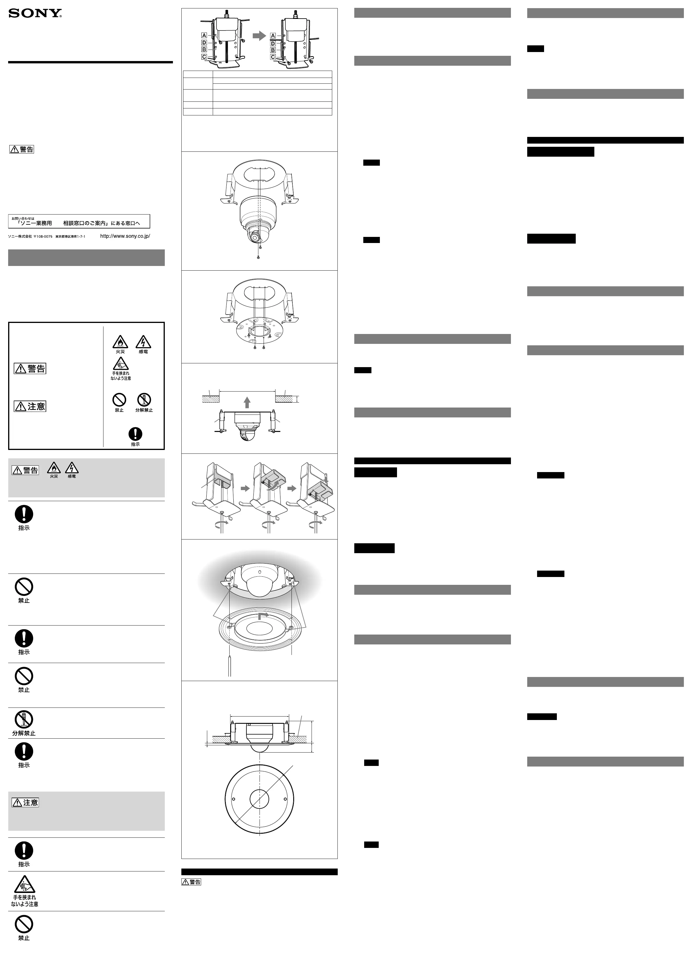
4
カメラの型に応じて、ブラケット固定位置をセットする
:
左右の金具の
ネジ(各2本)をはずし、取り外したネジを、表に示す正しいネジ穴に固
定する。(図
)
5
本機に付属の
M4
ネジを使って、天井埋め込み金具をカメラ本体、または
カメラに付属のブラケットに取り付ける。(図
)
◆
詳しくは、カメラの設置説明書や取扱説明書をご覧ください。
ご注意
本機の穴の中心と、カメラの底面またはカメラに付属のブラケット
の中心を合わせて取り付けてください。中心がずれていると、カ
バーが取り付けられない場合があります。
6
金具の左右にある固定板が縦になっていること(工場出荷状態)を確認
してから、カメラと金具が一体になったものを天井の穴に組み込む。(図
)
7
金具の左右のネジを締め、金具で天井を挟む。
ネジを締めると、縦になっていた固定板が外側へ回転して開きます。
さらにネジを締めると固定板が下がって天井を挟みます。(図
)
固定板が天井をしっかり挟んでいることを確認してください。
ご注意
ネジを締めるときは、
1.47N
・
m (15 kg f
・
cm)
以下のトルクで締め
てください。あまり強く締めると埋め込み金具が壊れることがありま
す。
8
カメラのスリットカバーを取りはずして、カメラの撮影方向や画角を調
整する。
調整が終わったらスリットカバーを元どおり取り付けます。
◆
詳しくは、カメラの設置説明書や取扱説明書をご覧ください。
9
ドームケースをカメラ本体に取り付ける。
◆
詳しくは、カメラの設置説明書や取扱説明書をご覧ください。
10
本機のカバーを取り付ける。(図
)
カバー内側の突起が金具にはめ込まれるようにカバーを回しながら取
り付け、カバーのネジ
2
本を締めます。
天井埋め込み金具のはずしかた
カバーのネジ
2
本をゆるめ、カバーを回して取りはずします。金具の左右の
固定板が縦になるまで左右のネジをゆるめてから、金具とカメラをはずしま
す。
ご注意
カバーは垂直方向にはずしてください。
ネジをゆるめるときのトルクは、
1.47N
・
m (15 kgf
・
cm)
以下にしてくださ
い。
ネジをゆるめるときはカメラを押さえてください。金具やカメラが落ち
る危険があります。
仕様
質量
約
850 g
(カバー含む)
外形寸法
図
をご覧ください。
付属品
テンプレート
(1)
、
M4
ネジ
(4)
、
取付説明書
(1)
English
WARNING
• This installation should be made by a qualified service person and
should conform to all local codes.
• Ensure that the installation location and its material are strong
enough to withstand the gross weight of the camera and the In-
Ceiling Bracket, and then install the camera securely. If they are not
strong enough, the camera may fall and cause serious injury.
• To prevent the camera from falling, be sure to attach the wire rope
supplied with the camera.
• If you install the camera at a height, check periodically, at least once a
year, to ensure that the connection has not loosened. If conditions
warrant, perform this periodic check more frequently.
CAUTION
• Check that the thickness of the ceiling is from 10 mm (
13
/
32
inches) to
35 mm (1
7
/16 inches) inclusive.
• Make a ø229 ± 2 mm (9
1
/8 ±
1
/16 inches) hole in the ceiling.
• Do not scratch your hands on the sharp edges; this may cause injury.
• Before attempting installation, wear gloves to prevent injury.
Overview
The YT-ICB45 is an in-ceiling bracket designed for use with Network Cameras
and Color Video Cameras. It is used when the body of the camera is
embedded in the ceiling, or with gypsum or plaster boards, where the
quality of the material used in the ceiling makes it difficult for ordinary
screws to hold.
The illustrations used in this manual show the SNC-DF50 series camera.
Installing the In-Ceiling Bracket
1
Make a ø 229 ± 2 mm (9
1
/8 ±
1
/16 inches) hole in the ceiling.
Use the supplied template. The four slotted holes on the template are
usable when you decide the center position of the camera.
2
Remove the dome casing from the camera.
For details, refer to the Installation Manual or the Operating Instructions of the
camera.
3
Connect the cables to the camera.
4
Set the bracket fixing position according to the camera model: Remove
the screws from the left and right side brackets (2 screws each) and fix
the removed screws in the proper screw holes that are informed in the
table. (Fig.
)
5
Using the supplied M4 screws, attach the In-Ceiling Bracket to the
camera’s unit casing or to the bracket supplied with the camera.
(Fig.
)
For details, refer to the Installation Manual or the Operating Instructions of the
camera.
Note
• Whenattaching,alignthecenteroftheholeontheIn-CeilingBracket
with the center of the bottom of the camera or the center of the
bracket supplied with the camera. The cover of the In-Ceiling Bracket
may not be attached if the centers are misaligned.
6
Be sure that the right and left fixing plates of the In-Ceiling Bracket stay
in the lengthwise position (factory setting), and install the In-Ceiling
Bracket with the camera on the ceiling. (Fig.
)
7
Tighten the left and right screws of the In-Ceiling Bracket to secure it to
the ceiling.
As you tighten the screws, the fixing plates swing outward and lower to
grip the ceiling. (Fig.
)
Be sure that the fixing plates grip the ceiling firmly.
Note
Torque the screws to 1.47 N•m (15 kgf•cm) or less to tighten them.
Tightening the screws too hard may cause damage to the In-Ceiling
Bracket.
8
Remove the slit cover, and adjust the shooting direction and range of
the camera.
After the adjustment, replace the slit cover.
For details, refer to the Installation Manual or the Operating Instructions of the
camera.
9
Attach the dome casing to the camera’s unit casing.
For details, refer to the Installation Manual or the Operating Instructions of the
camera.
10
Attach the cover of the In-Ceiling Bracket. (Fig.
)
Attach the cover while turning it so that the projections inside the
cover are inserted in the bracket, and tighten the two screws on the
cover.
Removing the In-Ceiling Bracket
Loosen the two screws on the cover and turn the cover to remove it.
Loosen the right and left screws of the In-Ceiling Bracket until the fixing
plates swing back lengthwise. Then remove the In-Ceiling Bracket and the
camera.
Notes
• Removethecoververtically.
• Torquethescrewsto1.47N
•m (15 kgf•cm) or less to loosen them.
Loosening the screws with excessive force may cause damage to the
In-Ceiling Bracket.
• Holdthecamerawhilelooseningthescrews;otherwisetheIn-Ceiling
Bracket and the camera may fall.
Specifications
Mass Approx. 850
g
(1 lb 14 oz)
Dimensions See Figure
.
Supplied accessories Template (1), M4 screws (4),
Installation Instructions (1)
Français
AVERTISSEMENT
• Cette installation doit être réalisée par du personnel qualifié et doit se
conformer à toutes les réglementations locales.
• Assurez-vous que l’emplacement et le support d’installation sont
suffisamment solides pour supporter le poids de la caméra et celui de
support de fixation, puis installez correctement la caméra. En cas de
résistance insuffisante, la camera risque de tomber et de provoquer
des blessures graves.
• Veillez à fixer le câble métallique fourni avec la caméra pour éviter
toute chute de la caméra.
• Si vous installez la caméra en hauteur, effectuez une verification
régulièrement, au moins une fois par an, afin de vous assurer que
l’ensemble n’est pas desserré. Dans la mesure du possible, effectuez
cette vérification plus fréquemment.
ATTENTION
• Vérifiez que l’épaisseur du plafond est comprise entre 10 mm
(
13
/32 pouces) et 35 mm (1
7
/16 pouces).
• Percez un trou de ø229 ± 2 mm (9
1
/8 ±
1
/16 pouces) dans le plafond.
• Ne passez pas les mains sur les bords coupants car vous pourriez vous
blesser.
• Avant de procéder à l’installation, enfilez des gants pour prévenir
toute blessure.
Aperçu
Le support YT-ICB45 est un support de fixation au plafond conçu pour être
utilisé avec les caméras réseau et les caméras vidéo couleur. Ce support est
nécessaire lorsque le corps de la caméra est incrusté dans le plafond ou
lorsque des plaques de plâtre sont utilisées et que la qualité du matériel
entrant dans la composition du plafond rend difficile la tenue de vis
ordinaires.
Les illustrations de ce manuel représentent une caméra de la série
SNC-DF50.
Mise en place du support de fixation au plafond
1
Percez un trou de 229 ± 2 mm (9
1
/8 ±
1
/16 pouces) de diamètre dans le
plafond.
Utilisez le modèle fourni. Vous pouvez utiliser les quatre trous du
modèle si vous choisissez la position centrale de la caméra.
2
Retirez le dôme de la caméra.
Pour plus de détails, reportez-vous au Manuel d’installation ou au Mode
d’emploi de la caméra.
3
Raccordez les câbles à la caméra.
4
Réglez la position de fixation du support selon le modèle de la caméra :
Retirez les vis des supports latéraux gauche et droit (deux vis sur
chacun), insérez ensuite ces vis dans les orifices appropriés comme
indiqué dans le tableau. (Figure
)
5
A l’aide des vis M4 fournies, attachez le support de fixation au plafond à
la caméra ou au socle fourni avec la caméra. (Figure
)
Pour plus de détails, reportez-vous au Manuel d’installation ou au Mode
d’emploi de la caméra.
Remarque
• Lorsdelaxation,alignezlecentredel’oricedusupportdexation
au plafond avec le centre de la partie inférieure de la camera ou le
centre du support fourni avec la camera. Il est possible que le
couvercledusupportdexationauplafondnepuissepasêtrexési
les centres sont mal alignés.
6
Assurez-vous que les plaques de fixation droite et gauche du support
de fixation au plafond restent dans le sens de la longueur (réglage
d’usine), puis installez le support de fixation au plafond avec la caméra
au plafond. (Figure
)
7
Resserrez les vis droite et gauche du support de fixation au plafond
pour le fixer fermement au plafond.
Lorsque vous resserrez les vis, les plaques de fixation basculent vers
l’extérieur et vers le bas pour adhérer au plafond. (Figure
)
Assurez-vous que les plaques de fixation adhèrent solidement au
plafond.
Remarque
Le couple de serrage des vis doit être de 1,47 N•m (15 kgf•cm) au
maximum. Un couple de serrage trop élevé risque d’endommager le
support de fixation au plafond.
8
Retirez le cache fendu, puis réglez la direction de prise de vue et la
portée de la caméra.
Une fois le réglage effectué, replacez le cache fendu.
Pour plus de détails, reportez-vous au Manuel d’installation ou au Mode
d’emploi de la caméra.
9
Fixez correctement le dôme à la caméra.
Pour plus de détails, reportez-vous au Manuel d’installation ou au Mode
d’emploi de la caméra.
10
Fixez le couvercle du support de fixation au plafond. (Figure
)
Fixez le couvercle tout en le tournant de sorte que les parties saillantes
à l’intérieur du couvercle soient insérées dans le support, puis serrez les
deux vis du couvercle.
Dépose du support de fixation au plafond
Desserrez les deux vis du couvercle et tournez le couvercle pour le retirer.
Desserrez les vis droite et gauche du support de fixation au plafond jusqu’à
ce que les plaques de fixation reprennent leur position dans le sens de la
longueur. Retirez ensuite le support de fixation au plafond et la caméra.
Remarques
• Retirezlecacheverticalement.
• Lecouplededesserragedesvisdoitêtrede1,47N
•m (15 kgf•cm) au
maximum. Le desserrage trop rapide des vis risque d’endommager le
support de fixation au plafond.
• Maintenezbienlacaméralorsquevousdesserrezlesvis,sinonlesupport
de fixation au plafond et la caméra risquent de tomber.
Spécifications
Masse 850 g (1 lb 14 oz) environ
Dimensions Voir Figure
.
Accessoires fournis Modèle (1), Vis M4 (4),
Manuel d’installation (1)
位置
/
Position/Position
モデル/Model/Modèle
SNC-DF50N, DF50P, DF80N, DF80P
SSC-CD75, CD75P, CD77, CD77P
SSC-CD79, CD79P
SNC-DS10, DS60, DM110, DM160
SSC-CD45, CD45P, CD47P, CD49, CD49P
SNC-VM602R, VM632R, EM602R, EM632R
上記以外のモデルはカメラの設置説明書や取扱説明書をご覧下さい。
For the model not listed above, refer to the Installation Manual or the Operating
Instrustions of the camera.
Si le modèle n’est pas indiqué dans la liste ci-dessus, reportez-vous au Manuel
d’installation ou au Mode d’emploi de la caméra.
M4ネジ
/ M4 screws / Vis M4
M4ネジ
/ M4 screws / Vis M4
固定板
/
Fixing
plate /
Plaque de
fixation
10~35/
10 to 35 (
13
/32
to 1
7
/16) /
10 à 35 (
13
/32 à
1
7
/16)
天井
/
Ceiling /
Plafond
直径φ
227
〜
231
の穴
/
ø227 to 231 (9 to 9
1
/8) hole /
Trou de ø227 à 231 (9 à 9
1
/8)
天井
/
Ceiling /
Plafond
固定板
/
Fixing
plate /
Plaque de
fixation
単位
:
ミリ
(
インチ
)
/ Unit: mm (inches) / Appareil : mm (pouces)
固定板
/
Fixing
plate /
Plaque
de fixation
11 (
7
/16)
天井
:
直径φ
227
〜
231
の穴
/
Ceiling: ø227 to 231 (9 to 9
1
/8) hole /
Plafond: Trou de ø227 à 231 (9 à 9
1
/8)
天井の厚さ
: 10~35
Thickness of the ceiling:
10 to 35 (
13
/32 to 1
7
/16) /
Epaisseur du plafond :
10 à 35 (
13
/32 à 1
7
/16)
100 (4)54 (2
1
/4)
ø270 (10
3
/4
)
単位
:
ミリ
(
インチ
)
/ Unit: mm (inches) / Unité : mm (pouces)
Product Specifications
| Brand: | Sony |
| Category: | Not categorized |
| Model: | YT-ICB45 |
Do you need help?
If you need help with Sony YT-ICB45, ask a question below and other users will answer you
Not categorized Sony User Manuals

26 October 2024
26 October 2024
24 October 2024
24 October 2024
24 October 2024
24 October 2024
24 October 2024
24 October 2024
24 October 2024
24 October 2024
Not categorized User Manuals
- Not categorized Candy
- Not categorized Electrolux
- Not categorized Samsung
- Not categorized Xiaomi
- Not categorized Casio
- Not categorized LG
- Not categorized Bosch
- Not categorized AEG
- Not categorized IKEA
- Not categorized Huawei
- Not categorized Braun
- Not categorized Brondi
- Not categorized HP
- Not categorized Philips
- Not categorized Panasonic
- Not categorized Bauknecht
- Not categorized BEKO
- Not categorized Delonghi
- Not categorized Daewoo
- Not categorized DeWalt
- Not categorized Epson
- Not categorized Etna
- Not categorized Teka
- Not categorized Apc
- Not categorized Balay
- Not categorized Siemens
- Not categorized Hama
- Not categorized Petsafe
- Not categorized Vorago
- Not categorized Neewer
- Not categorized Danby
- Not categorized Bartscher
- Not categorized Hartke
- Not categorized Bertazzoni
- Not categorized Gigabyte
- Not categorized Smeg
- Not categorized Hisense
- Not categorized Gree
- Not categorized Hoover
- Not categorized EBERLE
- Not categorized Hazet
- Not categorized Fluke
- Not categorized Goobay
- Not categorized Topeak
- Not categorized Antari
- Not categorized Thermex
- Not categorized TCL
- Not categorized Russell Hobbs
- Not categorized Panduit
- Not categorized IFM
- Not categorized Avantree
- Not categorized Royal Catering
- Not categorized Hotpoint
- Not categorized Whirlpool
- Not categorized Schwaiger
- Not categorized Nabo
- Not categorized Arendo
- Not categorized Megger
- Not categorized Balam Rush
- Not categorized Noxon
- Not categorized Sanus
- Not categorized Adidas
- Not categorized Domo
- Not categorized Cayin
- Not categorized Reflexion
- Not categorized TP Link
- Not categorized Inventum
- Not categorized Totolink
- Not categorized Shokz
- Not categorized Gamma
- Not categorized Artusi
- Not categorized Medel
- Not categorized Meris
- Not categorized D-Link
- Not categorized Navitel
- Not categorized Meridian
- Not categorized AeroCool
- Not categorized Kugoo
- Not categorized Rikon
- Not categorized Neff
- Not categorized Garmin
- Not categorized Razer
- Not categorized Teufel
- Not categorized Enermax
- Not categorized Noveen
- Not categorized StarTech.com
- Not categorized Origin Storage
- Not categorized Outwell
- Not categorized Best
- Not categorized Stihl
- Not categorized Kostal
- Not categorized ZOTAC
- Not categorized Comfee
- Not categorized Imarflex
- Not categorized Edgestar
- Not categorized Audient
- Not categorized Kogan
- Not categorized Solis
- Not categorized DJI
- Not categorized Snom
- Not categorized McIntosh
- Not categorized One For All
- Not categorized Caple
- Not categorized SereneLife
- Not categorized Roesle
- Not categorized APSystems
- Not categorized GoGEN
- Not categorized Festo
- Not categorized Create
- Not categorized Furrion
- Not categorized Oreg
- Not categorized Glorious
- Not categorized Pro-Ject
- Not categorized Yamaha
- Not categorized CaviLock
- Not categorized OOONO
- Not categorized Venom
- Not categorized Kichler
- Not categorized SMART Technologies
- Not categorized Neo
- Not categorized Newstar
- Not categorized Legrand
- Not categorized Integral LED
- Not categorized Goodram
- Not categorized Goldtouch
- Not categorized Lutec
- Not categorized Vello
- Not categorized Asus
- Not categorized Cudy
- Not categorized Hayter
- Not categorized BlueBuilt
- Not categorized Eufy
- Not categorized Gys
- Not categorized Conair
- Not categorized Turmix
- Not categorized Franke
- Not categorized Husqvarna
- Not categorized Sauber
- Not categorized Shimano
- Not categorized Axis
- Not categorized Tamron
- Not categorized Liebherr
- Not categorized Carson
- Not categorized Gourmetmaxx
- Not categorized Truelife
- Not categorized Busch-Jaeger
- Not categorized ETA
- Not categorized Voltcraft
- Not categorized Axor
- Not categorized Karran
- Not categorized Elkay
- Not categorized Varaluz
- Not categorized Extron
- Not categorized Lindy
- Not categorized Aputure
- Not categorized Netgear
- Not categorized Honor
- Not categorized XP-PEN
- Not categorized Danfoss
- Not categorized Riccar
- Not categorized Orbegozo
- Not categorized Media-tech
- Not categorized Kuppersbusch
- Not categorized Mebby
- Not categorized Pioneer
- Not categorized TONI&GUY
- Not categorized Summit
- Not categorized Accucold
- Not categorized EarFun
- Not categorized Toolcraft
- Not categorized Gram
- Not categorized Lorex
- Not categorized Catit
- Not categorized NuPrime
- Not categorized Ecler
- Not categorized Roccat
- Not categorized AudioControl
- Not categorized Elsner
- Not categorized Kask
- Not categorized Digitus
- Not categorized Cabasse
- Not categorized Koenic
- Not categorized Haier
- Not categorized Beaphar
- Not categorized Sure Petcare
- Not categorized Livall
- Not categorized Monogram
- Not categorized Sortimo
- Not categorized Unicol
- Not categorized Audio-Technica
- Not categorized Lian Li
- Not categorized JLab
- Not categorized Toa
- Not categorized Marantz
- Not categorized Knog
- Not categorized Rega
- Not categorized Vox
- Not categorized Mars Gaming
- Not categorized Kerbl
- Not categorized Metra
- Not categorized Pyle
- Not categorized Sencor
- Not categorized Hobby
- Not categorized Lenovo
- Not categorized Noctua
- Not categorized Klein Tools
- Not categorized LevelOne
- Not categorized Shure
- Not categorized Michael Todd Beauty
- Not categorized GRAUGEAR
- Not categorized Trixie
- Not categorized Schneider
- Not categorized Lorelli
- Not categorized Roland
- Not categorized OBSBOT
- Not categorized SuperTooth
- Not categorized Kluge
- Not categorized Bobrick
- Not categorized Signature Hardware
- Not categorized Martin
- Not categorized Kanto
- Not categorized Scott
- Not categorized Delta
- Not categorized Kindermann
- Not categorized Robern
- Not categorized Hortus
- Not categorized DeLock
- Not categorized Coyote
- Not categorized Kidde
- Not categorized Anker
- Not categorized Growatt
- Not categorized Nanoleaf
- Not categorized Grundig
- Not categorized Mistral
- Not categorized VMV
- Not categorized S.M.S.L
- Not categorized Privileg
- Not categorized MPM
- Not categorized PeakTech
- Not categorized Niceboy
- Not categorized Engenius
- Not categorized Khind
- Not categorized Amana
- Not categorized EMOS
- Not categorized CyberPower
- Not categorized KitchenAid
- Not categorized RGBlink
- Not categorized Clean Air Optima
- Not categorized Manfrotto
- Not categorized Exquisit
- Not categorized Cosatto
- Not categorized Fluval
- Not categorized Kicker
- Not categorized Gude
- Not categorized Auna
- Not categorized Taurus
- Not categorized Heatit
- Not categorized Midland
- Not categorized Field Optics
- Not categorized Zebra
- Not categorized Yealink
- Not categorized FIMI
- Not categorized Optex
- Not categorized Frigidaire
- Not categorized Levoit
- Not categorized Maytag
- Not categorized Deye
- Not categorized Nibe
- Not categorized Ryobi
- Not categorized Dremel
- Not categorized Breville
- Not categorized Kodak
- Not categorized Velleman
- Not categorized Sharkoon
- Not categorized RIDGID
- Not categorized Laserliner
- Not categorized Segway
- Not categorized Power Dynamics
- Not categorized DataVideo
- Not categorized RGV
- Not categorized Hendi
- Not categorized Gamdias
- Not categorized Concept
- Not categorized BeamZ
- Not categorized Livoo
- Not categorized Nexa
- Not categorized Guzzanti
- Not categorized XO
- Not categorized Steinel
- Not categorized Bluesound
- Not categorized Flex
- Not categorized Chauvin Arnoux
- Not categorized Blackstar
- Not categorized Caso
- Not categorized Kenwood
- Not categorized Cambridge
- Not categorized Nobo
- Not categorized Dell
- Not categorized Ciarra
- Not categorized Brandson
- Not categorized Mybeo
- Not categorized Aplic
- Not categorized CSL
- Not categorized Zoom
- Not categorized Tru Components
- Not categorized Bearware
- Not categorized Moen
- Not categorized Viewsonic
- Not categorized B-tech
- Not categorized IMM Photonics
- Not categorized Maginon
- Not categorized Speco Technologies
- Not categorized Nec
- Not categorized IFi Audio
- Not categorized Tripp Lite
- Not categorized Nevir
- Not categorized Infiniton
- Not categorized Ag Neovo
- Not categorized Henry Engineering
- Not categorized Taco Tuesday
- Not categorized Wire Technologies
- Not categorized GPO
- Not categorized Block
- Not categorized Maxi-Cosi
- Not categorized Ufesa
- Not categorized Milwaukee
- Not categorized Smart-AVI
- Not categorized CAME-TV
- Not categorized A-Designs
- Not categorized EchoMaster
- Not categorized Crimson
- Not categorized Elgato
- Not categorized Corsair
- Not categorized Generac
- Not categorized EVE
- Not categorized Dahua Technology
- Not categorized Cambium Networks
- Not categorized Safety 1st
- Not categorized Scarlett
- Not categorized Axxess
- Not categorized Advance
- Not categorized Indesit
- Not categorized Daikin
- Not categorized Shoprider
- Not categorized Canon
- Not categorized VAIS Technology
- Not categorized Maxsa
- Not categorized Lincoln Electric
- Not categorized BRIO
- Not categorized AXESS
- Not categorized DAB
- Not categorized Be Cool
- Not categorized Jocel
- Not categorized Bluetti
- Not categorized Blaupunkt
- Not categorized ORNO
- Not categorized Thermaltake
- Not categorized Artsound
- Not categorized Simrad
- Not categorized Volcano
- Not categorized Nordic Winter
- Not categorized TechBite
- Not categorized NEP
- Not categorized Catlink
- Not categorized Cablexpert
- Not categorized Ansmann
- Not categorized Røde
- Not categorized Makita
- Not categorized Einhell
- Not categorized Avidsen
- Not categorized Elac
- Not categorized Lewitt
- Not categorized Anova
- Not categorized Posiflex
- Not categorized Planet
- Not categorized Biostar
- Not categorized Mitsubishi
- Not categorized HeadRush
- Not categorized Showtec
- Not categorized PCE
- Not categorized Hikvision
- Not categorized Sitecom
- Not categorized Navman
- Not categorized JIMMY
- Not categorized Laica
- Not categorized Equip
- Not categorized Conceptronic
- Not categorized Sirius
- Not categorized Noyafa
- Not categorized Yorkville
- Not categorized Toro
- Not categorized Intermatic
- Not categorized Spear & Jackson
- Not categorized Tower
- Not categorized Hubble Connected
- Not categorized McGregor
- Not categorized Habitat
- Not categorized MSR
- Not categorized Entes
- Not categorized V-Tac
- Not categorized Salton
- Not categorized Novation
- Not categorized Chipolino
- Not categorized Alphatronics
- Not categorized Fezz
- Not categorized Eden
- Not categorized Fuxtec
- Not categorized Megasat
- Not categorized SolaX Power
- Not categorized Valcom
- Not categorized Mikrotik
- Not categorized Yale
- Not categorized Mosconi
- Not categorized Tristar
- Not categorized Mophie
- Not categorized Kohler
- Not categorized Envertec
- Not categorized Celly
- Not categorized Metabo
- Not categorized Jabra
- Not categorized Alphacool
- Not categorized Cuisinart
- Not categorized Doepke
- Not categorized Lupine
- Not categorized Anton/Bauer
- Not categorized Dometic
- Not categorized JBL
- Not categorized Rigol
- Not categorized Joy-it
- Not categorized Body Solid
- Not categorized DeepCool
- Not categorized Kali Audio
- Not categorized Chief
- Not categorized Majority
- Not categorized Cybex
- Not categorized Iiyama
- Not categorized Nedis
- Not categorized Sharp
- Not categorized Crock-Pot
- Not categorized Helix
- Not categorized Genesis
- Not categorized Dyson
- Not categorized Elation
- Not categorized Magmatic
- Not categorized Supermicro
- Not categorized Zendure
- Not categorized Logilink
- Not categorized Majestic
- Not categorized Basetech
- Not categorized Leviton
- Not categorized Soundstream
- Not categorized PAC
- Not categorized Xaoc
- Not categorized Eldom
- Not categorized Fisher And Paykel
- Not categorized Hohner
- Not categorized Britax
- Not categorized Elba
- Not categorized Steiner
- Not categorized Vonroc
- Not categorized Worx
- Not categorized Brentwood
- Not categorized Philco
- Not categorized Bellari
- Not categorized Rolls
- Not categorized MSI
- Not categorized Chauvet
- Not categorized Ordo
- Not categorized Ground Zero
- Not categorized OnePlus
- Not categorized V7
- Not categorized Jenn-Air
- Not categorized CRUX
- Not categorized Karma
- Not categorized Ridem
- Not categorized Glemm
- Not categorized StarIink
- Not categorized HomeCraft
- Not categorized Nostalgia
- Not categorized GameDay
- Not categorized X-Lite
- Not categorized Söll
- Not categorized Sparkle
- Not categorized Edouard Rousseau
- Not categorized Caberg
- Not categorized Exped
- Not categorized Igloo
- Not categorized Heusinkveld
- Not categorized KED
- Not categorized EPEVER
- Not categorized Grothe
- Not categorized Cane Creek
- Not categorized Swiss Eye
- Not categorized SilverStone
- Not categorized Goodis
- Not categorized TFA
- Not categorized X Rocker
- Not categorized Dreame
- Not categorized Foreo
- Not categorized Tesla
- Not categorized Aquael
- Not categorized Klarstein
- Not categorized Lauten Audio
- Not categorized Toddy
- Not categorized Lexivon
- Not categorized Icy Dock
- Not categorized Elta
- Not categorized ASI
- Not categorized Gurari
- Not categorized Varia
- Not categorized SPL
- Not categorized I-Tec
- Not categorized Xigmatek
- Not categorized Storcube
- Not categorized Tracer
- Not categorized Shark
- Not categorized REMKO
- Not categorized Phanteks
- Not categorized EnOcean
- Not categorized EK Water Blocks
- Not categorized Hoymiles
- Not categorized Envertech
- Not categorized Cougar
- Not categorized Asrock
- Not categorized Audiotec Fischer
- Not categorized Furman
- Not categorized Abac
- Not categorized Cata
- Not categorized Vivax
- Not categorized Black Diamond
- Not categorized Stanley
- Not categorized QSC
- Not categorized Bitspower
- Not categorized Black And Decker
- Not categorized Weston
- Not categorized Dobot
- Not categorized WHD
- Not categorized Schuberth
- Not categorized Q Acoustics
- Not categorized Scotsman
- Not categorized Radial Engineering
- Not categorized Karcher
- Not categorized Orion
- Not categorized A-NeuVideo
- Not categorized Beem
- Not categorized Logitech
- Not categorized Boneco
- Not categorized Atlona
- Not categorized EZ Dupe
- Not categorized Becken
- Not categorized DVDO
- Not categorized GoXtreme
- Not categorized Primacoustic
- Not categorized Avanti
- Not categorized Acros
- Not categorized Phil And Teds
- Not categorized Jotul
- Not categorized Thermarest
- Not categorized Dedra
- Not categorized Powerplus
- Not categorized Vivanco
- Not categorized TC Electronic
- Not categorized Suzuki
- Not categorized Bionaire
- Not categorized Huslog
- Not categorized Glem Gas
- Not categorized Apogee
- Not categorized Atomos
- Not categorized IOptron
- Not categorized Trevi
- Not categorized Palmer
- Not categorized R-Go Tools
- Not categorized Drayton
- Not categorized Spektrum
- Not categorized Jung
- Not categorized Götze & Jensen
- Not categorized Native Instruments
- Not categorized Homedics
- Not categorized Xvive
- Not categorized AMX
- Not categorized Perlick
- Not categorized Peavey
- Not categorized BenQ
- Not categorized Princess
- Not categorized FOX ESS
- Not categorized Waterstone
- Not categorized Mr Steam
- Not categorized Fresh N Rebel
- Not categorized DuroStar
- Not categorized Duromax
- Not categorized Owon
- Not categorized REVITIVE
- Not categorized Fosi Audio
- Not categorized Europalms
- Not categorized Sven
- Not categorized Global Water
- Not categorized Hamilton Beach
- Not categorized Extech
- Not categorized Tunturi
- Not categorized Craftsman
- Not categorized Gastronoma
- Not categorized Lumens
- Not categorized Brizo
- Not categorized Xinfrared
- Not categorized Getac
- Not categorized ProLights
- Not categorized Phonak
- Not categorized Cherub
- Not categorized Thor
- Not categorized Laurastar
- Not categorized Ambiano
- Not categorized Bissell
- Not categorized Antelope Audio
- Not categorized ESYLUX
- Not categorized Austral
- Not categorized LiveU
- Not categorized RF-Links
- Not categorized Fortinge
- Not categorized Mercury
- Not categorized Vaddio
- Not categorized InFocus
- Not categorized Stinger
- Not categorized NEXTO DI
- Not categorized Abus
- Not categorized AV Tool
- Not categorized Bauhn
- Not categorized Adventure Kings
- Not categorized EQ Acoustics
- Not categorized Michigan
- Not categorized Vent-A-Hood
- Not categorized Audix
- Not categorized Vizio
- Not categorized Livarno Lux
- Not categorized Grillmeister
- Not categorized Ernesto
- Not categorized Neno
- Not categorized Rommelsbacher
- Not categorized One Control
- Not categorized Bome
- Not categorized Redback Technologies
- Not categorized ESX
- Not categorized City Theatrical
- Not categorized Omnitronic
- Not categorized Reber
- Not categorized Kaiser Nienhaus
- Not categorized Crestron
- Not categorized Eurolite
- Not categorized Manhattan
- Not categorized Xavax
- Not categorized MOZA
- Not categorized Rocstor
- Not categorized Cruz
- Not categorized Newland
- Not categorized Edimax
- Not categorized Dragonshock
- Not categorized Russound
- Not categorized Adj
- Not categorized Olivetti
- Not categorized EVOLVEO
- Not categorized Stadler Form
- Not categorized Wolfcraft
- Not categorized Monacor
- Not categorized Heinner
- Not categorized Minolta
- Not categorized Sena
- Not categorized Innoliving
- Not categorized Aqara
- Not categorized POGS
- Not categorized Beghelli
- Not categorized BodyCraft
- Not categorized Superrollo
- Not categorized Mx Onda
- Not categorized Bixolon
- Not categorized Maruyama
- Not categorized Bravilor Bonamat
- Not categorized Hilti
- Not categorized D-Jix
- Not categorized Black Hydra
- Not categorized I.safe Mobile
- Not categorized Nimbus
- Not categorized Lowrance
- Not categorized Roxio
- Not categorized Accsoon
- Not categorized Inspire
- Not categorized Sebo
- Not categorized Boss
- Not categorized Tannoy
- Not categorized Prompter People
- Not categorized JL Audio
- Not categorized Edesa
- Not categorized IOIO
- Not categorized Genexis
- Not categorized Buzz Rack
- Not categorized ZKTeco
- Not categorized Giordani
- Not categorized Cadel
- Not categorized Dualit
- Not categorized Atlas Sound
- Not categorized Solo
- Not categorized Wagner
- Not categorized Bluestork
- Not categorized Davis
- Not categorized Comica
- Not categorized AddLiving
- Not categorized Melitta
- Not categorized Lowell
- Not categorized INOGENI
- Not categorized Nearity
- Not categorized Kiloview
- Not categorized Middle Atlantic
- Not categorized Mount-It!
- Not categorized Morley
- Not categorized Ampeg
- Not categorized Apantac
- Not categorized Carry-on
- Not categorized Liftmaster
- Not categorized GVision
- Not categorized IPGARD
- Not categorized Murideo
- Not categorized TK Audio
- Not categorized Rosco
- Not categorized Proaim
- Not categorized Cisco
- Not categorized CGV
- Not categorized Vacmaster
- Not categorized Elmo
- Not categorized Libec
- Not categorized Point Source Audio
- Not categorized Macally
- Not categorized Ade
- Not categorized MooreCo
- Not categorized Di4
- Not categorized Mellerware
- Not categorized Zenec
- Not categorized Silver Cross
- Not categorized American DJ
- Not categorized AJA
- Not categorized Postium
- Not categorized RME
- Not categorized SurgeX
- Not categorized Alcon
- Not categorized Vantec
- Not categorized Silverline
- Not categorized VAVA
- Not categorized Vicoustic
- Not categorized LERAN
- Not categorized Doffler
- Not categorized Profoto
- Not categorized TensCare
- Not categorized Scanstrut
- Not categorized Industrial Music Electronics
- Not categorized Source Audio
- Not categorized Black Lion Audio
- Not categorized Wiha
- Not categorized Puls Dimension
- Not categorized Wasp
- Not categorized Gamewright
- Not categorized ISDT
- Not categorized Ilve
- Not categorized Reolink
- Not categorized Bebob
- Not categorized Ashly
- Not categorized Claypaky
- Not categorized Premier Mounts
- Not categorized MuxLab
- Not categorized Icy Box
- Not categorized Holosun
- Not categorized Seagate
- Not categorized Holzmann
- Not categorized Blackmagic Design
- Not categorized Audiolab
- Not categorized Modbap Modular
- Not categorized Genius
- Not categorized Rommer
- Not categorized Traeger
- Not categorized Memphis Audio
- Not categorized Focal
- Not categorized Belkin
- Not categorized BDI
- Not categorized Alpine
- Not categorized Ring
- Not categorized TomTom
- Not categorized XGIMI
- Not categorized Omron
- Not categorized Starlink
- Not categorized Celestron
- Not categorized Gymform
- Not categorized Glide Gear
- Not categorized Oppo
- Not categorized Chicco
- Not categorized AVM
- Not categorized Impact
- Not categorized Pelco
- Not categorized FoxFury
- Not categorized Mammut
- Not categorized Heritage Audio
- Not categorized Safco
- Not categorized Monoprice
- Not categorized Stabila
- Not categorized CTA Digital
- Not categorized Olight
- Not categorized Primo
- Not categorized HammerSmith
- Not categorized Cyrus
- Not categorized Roadinger
- Not categorized Steelbody
- Not categorized Ventev
- Not categorized Elektrobock
- Not categorized Triton
- Not categorized Trisa
- Not categorized Corberó
- Not categorized Korg
- Not categorized Atosa
- Not categorized STANDIVARIUS
- Not categorized Avteq
- Not categorized Izzy
- Not categorized PureLink
- Not categorized UNYKAch
- Not categorized Al-ko
- Not categorized ADATA
- Not categorized Mobotix
- Not categorized Kramer
- Not categorized ATen
- Not categorized Blustream
- Not categorized Laserworld
- Not categorized Kunft
- Not categorized Milesight
- Not categorized Spanninga
- Not categorized Bialetti
- Not categorized Xlyne
- Not categorized Plant Craft
- Not categorized Sungrow
- Not categorized Grundfos
- Not categorized Bazooka
- Not categorized Carlsbro
- Not categorized MoFi
- Not categorized Blackburn
- Not categorized Bang And Olufsen
- Not categorized Sole Fitness
- Not categorized Cowon
- Not categorized Bebe Confort
- Not categorized WHALE
- Not categorized Stalco
- Not categorized Horizon Fitness
- Not categorized Sonel
- Not categorized Jilong
- Not categorized Tenda
- Not categorized Maytronics
- Not categorized Tempmate
- Not categorized Idec
- Not categorized Analog Way
- Not categorized Gamesir
- Not categorized ZyXEL
- Not categorized Vogue
- Not categorized Frilec
- Not categorized Yaesu
- Not categorized Concept2
- Not categorized Musical Fidelity
- Not categorized Flir
- Not categorized Rademacher
- Not categorized NGS
- Not categorized CTOUCH
- Not categorized RCF
- Not categorized Microchip
- Not categorized Homematic IP
- Not categorized Tektronix
- Not categorized WilTec
- Not categorized Thomson
- Not categorized Easypix
- Not categorized LC-Power
- Not categorized SVS
- Not categorized 8BitDo
- Not categorized Pardini
- Not categorized Audeze
- Not categorized Everdure
- Not categorized Insta360
- Not categorized Fieldmann
- Not categorized Alpen Kreuzer
- Not categorized Xplora
- Not categorized H.Koenig
- Not categorized Aiwa
- Not categorized Wimberley
- Not categorized Insignia
- Not categorized Playtive
- Not categorized Vimar
- Not categorized Osprey
- Not categorized Hosa
- Not categorized Havis
- Not categorized Emerson
- Not categorized Weasy
- Not categorized Biltema
- Not categorized Bogen
- Not categorized Electro Harmonix
- Not categorized Vocopro
- Not categorized Chrome-Q
- Not categorized Galaxy Audio
- Not categorized Altman
- Not categorized Aiphone
- Not categorized Atlas
- Not categorized Graco
- Not categorized Manta
- Not categorized MARTOR
- Not categorized Mean Well
- Not categorized HMS Premium
- Not categorized Exelpet
- Not categorized Trendnet
- Not categorized G-Technology
- Not categorized CubuSynth
- Not categorized Simpson
- Not categorized Infasecure
- Not categorized SecureSafe
- Not categorized Intellinet
- Not categorized Hikoki
- Not categorized Solac
- Not categorized Emerio
- Not categorized Butler
- Not categorized AVer
- Not categorized IK Multimedia
- Not categorized Vankyo
- Not categorized Murr Elektronik
- Not categorized TDK-Lambda
- Not categorized Vitek
- Not categorized Quantum
- Not categorized Texas
- Not categorized ProfiCook
- Not categorized Arovec
- Not categorized Acti
- Not categorized GMB Gaming
- Not categorized Cadac
- Not categorized Olympia
- Not categorized Osram
- Not categorized Patching Panda
- Not categorized Consul
- Not categorized Manitowoc
- Not categorized Joranalogue
- Not categorized Klavis
- Not categorized HyperX
- Not categorized Zhiyun
- Not categorized ChamSys
- Not categorized OneTouch
- Not categorized Kospel
- Not categorized Crosscall
- Not categorized Dynacord
- Not categorized Rapoo
- Not categorized Suunto
- Not categorized Roidmi
- Not categorized Aconatic
- Not categorized IOGEAR
- Not categorized Ferguson
- Not categorized DAP Audio
- Not categorized Artecta
- Not categorized IBEAM
- Not categorized Mattel
- Not categorized Baby Jogger
- Not categorized Healthy Choice
- Not categorized Yato
- Not categorized Porter-Cable
- Not categorized Christmas Time
- Not categorized Barazza
- Not categorized Chacon
- Not categorized Marmitek
- Not categorized Dehner
- Not categorized Seaward
- Not categorized Eliminator Lighting
- Not categorized NordicTrack
- Not categorized Microboards
- Not categorized CEDAR
- Not categorized JoeCo
- Not categorized BZBGear
- Not categorized Fiilex
- Not categorized Gen Energy
- Not categorized DEERSYNC
- Not categorized Cranborne Audio
- Not categorized ChyTV
- Not categorized Bresser
- Not categorized Arkon
- Not categorized Apollo Design
- Not categorized Tactical Fiber Systems
- Not categorized Telmax
- Not categorized Sonifex
- Not categorized Blanco
- Not categorized ARC
- Not categorized Cardo
- Not categorized President
- Not categorized Galcon
- Not categorized K&M
- Not categorized Xcellon
- Not categorized Trijicon
- Not categorized Vortex
- Not categorized Vertex
- Not categorized PTZ Optics
- Not categorized Sescom
- Not categorized Robus
- Not categorized Revic
- Not categorized Panamax
- Not categorized Kahayan
- Not categorized Nureva
- Not categorized Pawa
- Not categorized MSW
- Not categorized Ulsonix
- Not categorized Stamony
- Not categorized Fujifilm
- Not categorized ColorKey
- Not categorized Stamina
- Not categorized Lemair
- Not categorized Leica
- Not categorized Soundsphere
- Not categorized Core SWX
- Not categorized DBX
- Not categorized Titanwolf
- Not categorized Perfect Christmas
- Not categorized Medicinalis
- Not categorized Uplink
- Not categorized Rupert Neve Designs
- Not categorized GPX
- Not categorized Flama
- Not categorized Thorens
- Not categorized Microair
- Not categorized XCell
- Not categorized Tepro
- Not categorized Traco Power
- Not categorized Yellow Garden Line
- Not categorized Vogels
- Not categorized Microsoft
- Not categorized Newline
- Not categorized Liam&Daan
- Not categorized Primewire
- Not categorized Rittal
- Not categorized Snow Joe
- Not categorized Phoenix Gold
- Not categorized Universal Audio
- Not categorized Soundmaster
- Not categorized Casa Deco
- Not categorized Adventuridge
- Not categorized Antec
- Not categorized Nutrichef
- Not categorized Parkside
- Not categorized Inverx
- Not categorized Ugreen
- Not categorized Haeger
- Not categorized Cleanmaxx
- Not categorized Victrola
- Not categorized Google
- Not categorized Gloria
- Not categorized Steinberg
- Not categorized EAT
- Not categorized Vincent
- Not categorized Ernitec
- Not categorized Jinbei
- Not categorized Interstuhl
- Not categorized Wachendorff
- Not categorized Geneva
- Not categorized Alfatron
- Not categorized Rockford Fosgate
- Not categorized Sumiko
- Not categorized Chamberlain
- Not categorized Walrus Audio
- Not categorized Govee
- Not categorized Foscam
- Not categorized Ambient Weather
- Not categorized Anybus
- Not categorized Gra-Vue
- Not categorized Enhance
- Not categorized Digitalinx
- Not categorized Easyrig
- Not categorized Bolt
- Not categorized Comprehensive
- Not categorized Ocean Way Audio
- Not categorized Ocean Matrix
- Not categorized Peerless-AV
- Not categorized Blomberg
- Not categorized MAK
- Not categorized Deaf Bonce
- Not categorized Easymaxx
- Not categorized Christmaxx
- Not categorized Fiio
- Not categorized Multibrackets
- Not categorized Hanseatic
- Not categorized Evenflo
- Not categorized ADDAC System
- Not categorized Primera
- Not categorized Hecate
- Not categorized Alutruss
- Not categorized LightZone
- Not categorized Peak Design
- Not categorized Blizzard
- Not categorized Drawmer
- Not categorized EOTech
- Not categorized Edelkrone
- Not categorized Ergotools Pattfield
- Not categorized ESE
- Not categorized OKAY
- Not categorized Uniropa
- Not categorized JMAZ Lighting
- Not categorized AEA
- Not categorized NightStick
- Not categorized Aguilar
- Not categorized JK Audio
- Not categorized Sabrent
- Not categorized MIOPS
- Not categorized Hawke
- Not categorized Rotatrim
- Not categorized Defender
- Not categorized Enttec
- Not categorized Robinhood
- Not categorized GVM
- Not categorized Feelworld
- Not categorized Eller
- Not categorized Arthur Martin
- Not categorized Theben
- Not categorized Soundcraft
- Not categorized Martin Logan
- Not categorized Andover
- Not categorized Fortinet
- Not categorized Prestigio
- Not categorized Deity
- Not categorized Watson
- Not categorized Grimm Audio
- Not categorized AVMATRIX
- Not categorized Grunkel
- Not categorized CMI
- Not categorized Synco
- Not categorized Betty Bossi
- Not categorized Lanaform
- Not categorized CAD Audio
- Not categorized Moulinex
- Not categorized Kubo
- Not categorized Merging
- Not categorized Livington
- Not categorized Hurricane
- Not categorized Akai
- Not categorized AirTurn
- Not categorized New Pol
- Not categorized Expressive E
- Not categorized Amazfit
- Not categorized ILive
- Not categorized Giardino
- Not categorized Flycam
- Not categorized Digigram
- Not categorized Mutec
- Not categorized Senal
- Not categorized Ipevo
- Not categorized Tempo
- Not categorized Proviel
- Not categorized Xblitz
- Not categorized Kathrein
- Not categorized Mafell
- Not categorized Aspes
- Not categorized Tineco
- Not categorized Zelmer
- Not categorized Autel
- Not categorized Mercusys
- Not categorized Velbus
- Not categorized Connection
- Not categorized HuddleCamHD
- Not categorized Technical Pro
- Not categorized Solplanet
- Not categorized JOBY
- Not categorized Raya
- Not categorized Hammond
- Not categorized DOD
- Not categorized Marshall Electronics
- Not categorized Videotel Digital
- Not categorized Avenview
- Not categorized Bretford
- Not categorized Badiona
- Not categorized Dangerous Music
- Not categorized Smith-Victor
- Not categorized Zylight
- Not categorized Blind Spot
- Not categorized BIOS Living
- Not categorized Burris
- Not categorized Kemo
- Not categorized MBM
- Not categorized TAURUS Titanium
- Not categorized Gardenline
- Not categorized Millennia
- Not categorized Suntec
- Not categorized PCE Instruments
- Not categorized AREXX
- Not categorized Blue Sky
- Not categorized 3M
- Not categorized Rocktrail
- Not categorized BeSafe
- Not categorized American International
- Not categorized T-Rex
- Not categorized Computherm
- Not categorized Babysense
- Not categorized Bora
- Not categorized Hayward
- Not categorized Thinkware
- Not categorized Cloud
- Not categorized Apricorn
- Not categorized Lucide
- Not categorized Foster
- Not categorized Mulex
- Not categorized Comfortisse
- Not categorized Intertechno
- Not categorized EQ-3
- Not categorized Yphix
- Not categorized Magliner
- Not categorized Em-Trak
- Not categorized Black Box
- Not categorized Albert Heijn
- Not categorized Infantino
- Not categorized Bestgreen
- Not categorized Lenoxx
- Not categorized Empress Effects
- Not categorized Hacienda
- Not categorized Dali
- Not categorized Cooler Master
- Not categorized Enbrighten
- Not categorized Audison
- Not categorized Flame
- Not categorized UDG Gear
- Not categorized Lastolite
- Not categorized Weidmüller
- Not categorized NANO Modules
- Not categorized Scala
- Not categorized EA Elektro Automatik
- Not categorized Minox
- Not categorized Gustard
- Not categorized Technaxx
- Not categorized Bahr
- Not categorized Grand Effects
- Not categorized Franklin
- Not categorized Sodapop
- Not categorized Absco
- Not categorized Bestway
- Not categorized 4ms
- Not categorized Arturia
- Not categorized Vivolink
- Not categorized Victor Technology
- Not categorized Lowepro
- Not categorized Pitsos
- Not categorized Celexon
- Not categorized Neumärker
- Not categorized SunPower
- Not categorized Black Line
- Not categorized RCBS
- Not categorized Hensel
- Not categorized Ultimate
- Not categorized Westland
- Not categorized Casablanca
- Not categorized For_Q
- Not categorized Pro-User
- Not categorized Flavel
- Not categorized Sekonic
- Not categorized Deltaco Gaming
- Not categorized Bluebird
- Not categorized Babybjörn
- Not categorized Dunlop
- Not categorized Starlyf
- Not categorized WEG
- Not categorized Cotek
- Not categorized Deditec
- Not categorized Forza
- Not categorized Yamazen
- Not categorized Lantus
- Not categorized Edwards
- Not categorized FireAngel
- Not categorized Instant
- Not categorized Truetone
- Not categorized Carlo Gavazzi
- Not categorized PurAthletics
- Not categorized Jane
- Not categorized OLLO
- Not categorized Yuer
- Not categorized Gustavsberg
- Not categorized The Joy Factory
- Not categorized Kwantum
- Not categorized Teia
- Not categorized MyPOS
- Not categorized Altrad
- Not categorized Gator Frameworks
- Not categorized KNEKT
- Not categorized Durvet
- Not categorized Favero
- Not categorized HDFury
- Not categorized LEDs-ON
- Not categorized Schatten Design
- Not categorized Statron
- Not categorized Baninni
- Not categorized GW Instek
- Not categorized Aim TTi
- Not categorized Ketron
- Not categorized Bbf
- Not categorized AURALiC
- Not categorized Code
- Not categorized Mivar
- Not categorized Pressalit
- Not categorized IStarUSA
- Not categorized Dreamgear
- Not categorized Vitalmaxx
- Not categorized Saramonic
- Not categorized SHX
- Not categorized Televés
- Not categorized Applico
- Not categorized Hegel
- Not categorized TOGU
- Not categorized Dash
- Not categorized Futurelight
- Not categorized JANDY
- Not categorized ResMed
- Not categorized Jungle Gym
- Not categorized Baby Lock
- Not categorized Sheeran Looper
- Not categorized Akasa
- Not categorized Bavaria By Einhell
- Not categorized Oregon Scientific
- Not categorized Glyph
- Not categorized Enphase
- Not categorized Gem Toys
- Not categorized Plasma Cloud
- Not categorized Mega
- Not categorized Viomi
- Not categorized United Office
Latest Not categorized User Manuals

27 October 2024
27 October 2024
27 October 2024
27 October 2024
27 October 2024
27 October 2024
27 October 2024
27 October 2024
27 October 2024
27 October 2024