PCE Instruments PCE-DPD-U Manual
PCE Instruments
Measuring equipment
PCE-DPD-U
Read below 📖 the manual in Italian for PCE Instruments PCE-DPD-U (28 pages) in the Measuring equipment category. This guide has been helpful for 18 people and has been rated 4.5 stars on average by 2 users
Page 1/28
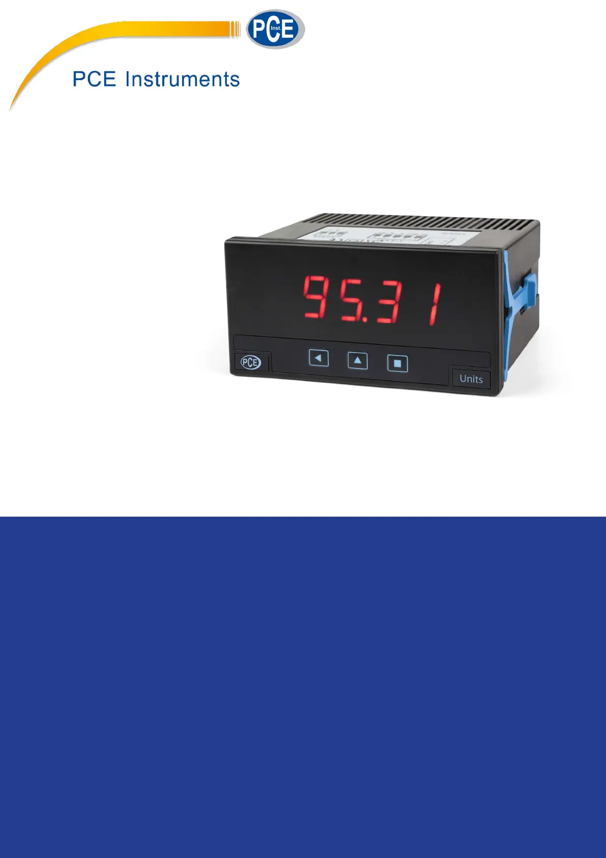
PCE-DPD-U
Mulsignal panel meter
Mulsignal digital panel meter, congurable to work as AC and DC voltmeter (up to 600 Vac / dc), AC and DC
ammeter (up to 5 Aac / dc), accepts process signals (mA, Vdc), thermocouples, resisve temperature probes
(Pt, Ni, PTC and NTC), resistances, potenometers and frequency. Congurable. Standard 96 x 48 mm size
(1/8 DIN). Scalable reading with 4 digits (9999 / -1999). ‘Fast access’ funcon to alarm setpoints, ‘external
control’ to acvate predened funcons, ‘Eco’ mode for low consumpon, selectable dual scaling, 5 levels
of congurable brightness. Single universal power supply 18 to 265 Vac/dc. Oponal modules for output
and control (relays, analog output, Modbus RTU).
User’s Manual
PANEL METERS
4822r06
www.pce-instruments.com

2
PCE Instruments PCE Instruments | www.pce-instruments.com
1. Panel meter PCE-DPD-U
Mulsignal 96 x 48 mm panel meter
Mulsignal digital panel meter in 96 x 48 mm size (1/8 DIN). Accepts
AC and DC voltage signals from mV up to 600 V and currents up to
5 A (AC measures in True RMS), process signals (mA and Vdc) with
excitaon voltage included, thermocouples K, J, E, N, L, R, S, B, T and
C, resisve temperature probes (Pt100, Pt500, Pt1000, Ni100, Ni200,
Ni1000, PTC and NTC), resistances, potenometers and frequency.
Scalable reading with 4 digits up to 9999 / -1999 with congurable
decimal point. Two independent alarms, congurable as maximum
or minimum, with hysteresis and setpoint.
Oponal 1 or 2 relay outputs, 4/20 mA isolated analog output, and
Modbus RTU isolated serial communicaons.
Front protecon IP50, with oponal IP65. Connecons with plug-in
screw terminals.
Index
1. Panel meter PCE-DPD-U . . . . . . . . . . . . . . . . . . . . 2
1.1 How to order . . . . . . . . . . . . . . . . . . . . . . . . 2
1.2 Front view . . . . . . . . . . . . . . . . . . . . . . . . . . 3
1.3 Rear view . . . . . . . . . . . . . . . . . . . . . . . . . . 3
1.4 Power connecons . . . . . . . . . . . . . . . . . . . . . 3
1.5 Signal connecons . . . . . . . . . . . . . . . . . . . . . 3
1.6 Mechanical dimensions (mm) . . . . . . . . . . . . . . . 3
1.7 Installaon and start-up . . . . . . . . . . . . . . . . . . 3
1.8 Technical specicaons . . . . . . . . . . . . . . . . . . 4
1.9 Internal jumpers . . . . . . . . . . . . . . . . . . . . . . 5
1.10 Measuring AC voltages and AC currents. . . . . . . . . 6
1.11 Measuring DC voltages and DC currents . . . . . . . . 7
1.12 Measuring thermocouples . . . . . . . . . . . . . . . . 8
1.13 Measuring with Pt and Ni probes . . . . . . . . . . . . 9
1.14 Measuring with NTC probes . . . . . . . . . . . . . . .10
1.15 Measuring with PTC probes . . . . . . . . . . . . . . .10
1.16 Process measures . . . . . . . . . . . . . . . . . . . . . 11
1.17 Measuring frequency . . . . . . . . . . . . . . . . . . . 11
1.18 Measuring resistances . . . . . . . . . . . . . . . . . .12
1.19 Measuring potenometers. . . . . . . . . . . . . . . . 12
1.20 ‘Fast access’ menu . . . . . . . . . . . . . . . . . . . .13
1.21 Scaling . . . . . . . . . . . . . . . . . . . . . . . . . . .13
1.22 Oset reading . . . . . . . . . . . . . . . . . . . . . . .13
1.23 ‘Eco’ mode . . . . . . . . . . . . . . . . . . . . . . . . . 13
1.24 External control . . . . . . . . . . . . . . . . . . . . . . 13
1.25 Second scaling . . . . . . . . . . . . . . . . . . . . . . . 13
1.26 To open the instrument. . . . . . . . . . . . . . . . . . 14
1.27 How to operate the menus. . . . . . . . . . . . . . . . 15
1.28 Messages and errors . . . . . . . . . . . . . . . . . . .15
1.29 Conguraon menu. . . . . . . . . . . . . . . . . . . . 16
1.29.1 Input signal ranges . . . . . . . . . . . . . . . . . .16
1.29.2 Scaling . . . . . . . . . . . . . . . . . . . . . . . . .17
1.29.3 Alarms . . . . . . . . . . . . . . . . . . . . . . . . .17
1.29.4 Fast access . . . . . . . . . . . . . . . . . . . . . . . 18
1.29.5 Super fast access . . . . . . . . . . . . . . . . . . .18
1.29.6 External control . . . . . . . . . . . . . . . . . . . . 18
1.29.7 Menu ‘Tools’ . . . . . . . . . . . . . . . . . . . . . . 19
1.29.8 Conguring the opons. . . . . . . . . . . . . . . . 21
1.30 Full conguraon menu . . . . . . . . . . . . . . . . .22
1.31 Precauons on installaon . . . . . . . . . . . . . . . . 25
1.32 Factory conguraon . . . . . . . . . . . . . . . . . . . 25
1.33 Warranty . . . . . . . . . . . . . . . . . . . . . . . . . . 25
1.34 CE declaraon of conformity . . . . . . . . . . . . . . . 25
2. Output and control modules . . . . . . . . . . . . . . . . .26
2.1 Modules PCE-DPD-U/R1 and PCE-DPD-U/R2 (relay output) . 26
2.2 Module PCE-DPD-U/A1 (analog output) . . . . . . . . .26
2.3 Module PCE-DPD-U/MB1 (Modbus RTU) . . . . . . . . . 27
Instrument designed for industrial use, highly exible, allows for in-
tegraon in mulple applicaons, reduced cost, excellent quality and
oponal customizaon available.
• ‘Fast access’ menu at front key UP (5) congurable for fast access
to alarm setpoints (see secon 1.20).
• ‘Eco’ mode reduces power consumpon
(see secon 1.23).
• Simplied scaling conguraon (see secon 1.21).
• Funcon ‘external control’ to acvate with a contact a predened
funcon (second scaling, decimal point, reading ‘hold’, ‘tare’, memo-
ry of maximum or minimum) (see secon 1.24).
• 5 congurable brightness levels (see secon 1.29.7).
1.1 How to order
PCE-DPD
Model Opon 1
U - -
-R1 (1 relay)
-A1 (analog output)
-MB1 (Modbus RTU)
-(empty)
-U
(Power supply
18...265 Vac/dc)
-
Opon 2
-R2 (1 relay)
-(empty)

3
PCE Instruments PCE Instruments | www.pce-instruments.com
1.2 Front view
1.4 Power connecons
1.5 Signal connecons
Key ‘UP’
Logo Units
Key ‘SQ’
Key ‘LE’
‘Conguraon menu’
(see secon 1.29)
‘Fast access‘
(see secon 1.29.4)
1.3 Rear view
Signal
(see secon 1.5)
Opon 2 Opon 1
Power
(see secon 1.4)
12345 890
Detail of the plug-in screw terminals provided with
the instrument. The instrument is provided with all
terminals needed, both male and female.
Alarm 1
Alarm 2
Earth connecon - The instru-
ment does not need earth con-
necon for correct operaon nor
for compliance with security reg-
ulaons. Terminal 9 is is not con-
nected to any internal circuit and
is provided only as a safe place
for earth wire.
Fuse - This instrument has not internal fuse. Conforming to security
regulaon 61010-1, add a protecon fuse to the power line to act as
disconnecon element, easily accessible to the operator and iden-
ed as a protecon device.
250 mA me-lag for power voltage > 50 Vac/dc
400 mA me-lag for power voltage < 50 Vac/dc
~
8 9 0
-
+
~
Power 18 to 265 Vac/dc
Signals up to 600 V and 200 V (AC and DC) must be connected at
terminals 1 and 4. Signals for 5 A current (AC and DC) must be con-
nected at terminals 3 and 4. All other signals must be connected
between terminals 2 and 4. Terminal 5 is a ‘mulfuncon’ terminal,
congurable with one of the following funcons :
• +15 Vdc excitaon voltage (Vexc) for process signals
• +5 Vdc excitaon for potenometer signals
• connecon for the Pt100 third wire compensaon
• external contact ‘EK’ funcon
To select the terminal 5 funcon, select the posion of internal jump-
er ‘T’
(see secon 1.9)
.
44
92
Panel
cut-out
16
8
75
96
48
1.6 Mechanical dimensions (mm)
HV signal
5 A
{
{
~Vac, ±Vdc, resistance, mA, pot,
thermocouple+, Pt+, Ni+, PTC+, NTC+
{
Signal
~600 Vac, ~200 Vac
±600 Vdc, ±200 Vdc
~5 Aac, ±5 Adc
Common
{
neutral, 0 V, common
12345
mulfunc.
{
Vexc, Pt100 3 wire, Pot+,
‘EK’ external control
1. Open the instrument as indicated at secon 1.26 and access
the internal board.
2. Select jumpers ‘S’ for the signal range required (see secon
1.9).
3. Select jumper ‘T’ to assign to mulfuncon terminal 5 the re-
quired funconality (see secon 1.9).
4. Close the instrument ad indicated at secon 1.26.
5. Connect the input signal and the power supply as indicated at
secons 1.4 and 1.5.
6. Enter the ‘conguraon menu’ to congure the instrument
(scaling, alarms, ...) (see secon 1.29).
1.7 Installaon and start-up
Units
Units
Product Specifications
| Brand: | PCE Instruments |
| Category: | Measuring equipment |
| Model: | PCE-DPD-U |
Do you need help?
If you need help with PCE Instruments PCE-DPD-U, ask a question below and other users will answer you
Measuring equipment PCE Instruments User Manuals

24 October 2024
22 October 2024
22 October 2024
22 October 2024
22 October 2024
22 October 2024
22 October 2024
22 October 2024
22 October 2024
22 October 2024
Measuring equipment User Manuals
- Measuring equipment EBERLE
- Measuring equipment Hazet
- Measuring equipment Fluke
- Measuring equipment Megger
- Measuring equipment Kogan
- Measuring equipment AkYtec
- Measuring equipment Voltcraft
- Measuring equipment Klein Tools
- Measuring equipment PeakTech
- Measuring equipment Clean Air Optima
- Measuring equipment Flex
- Measuring equipment CSL
- Measuring equipment Elgato
- Measuring equipment Kern
- Measuring equipment Be Cool
- Measuring equipment ORNO
- Measuring equipment Einhell
- Measuring equipment Mitsubishi
- Measuring equipment Noyafa
- Measuring equipment Megasat
- Measuring equipment Reely
- Measuring equipment Joy-it
- Measuring equipment Logilink
- Measuring equipment Basetech
- Measuring equipment Gossen Metrawatt
- Measuring equipment TFA
- Measuring equipment Owon
- Measuring equipment Extech
- Measuring equipment Milesight
- Measuring equipment Sonel
- Measuring equipment Flir
- Measuring equipment Testo
- Measuring equipment MSW
- Measuring equipment Stamos
- Measuring equipment Ideal
- Measuring equipment Hikmicro
- Measuring equipment Siglent
- Measuring equipment Kopp
- Measuring equipment PICO
- Measuring equipment Enda
- Measuring equipment Wachendorff
- Measuring equipment Ermenrich
- Measuring equipment Beha-Amprobe
- Measuring equipment Adwa
- Measuring equipment Tempo
- Measuring equipment Vemer
- Measuring equipment Testboy
- Measuring equipment Duro Pro
- Measuring equipment Kyoritsu
- Measuring equipment Benning
- Measuring equipment MASIMO
- Measuring equipment Stahlwille
- Measuring equipment SHX
Latest Measuring equipment User Manuals
27 October 2024
27 October 2024
27 October 2024
27 October 2024
27 October 2024
27 October 2024
27 October 2024
27 October 2024
27 October 2024
27 October 2024