Potter FASPKR Manual
Read below 📖 the manual in Italian for Potter FASPKR (8 pages) in the Speaker category. This guide has been helpful for 24 people and has been rated 4.5 stars on average by 2 users
Page 1/8
FASPKR & SPKSTR-24CLP SERIES
ANSI/UL AND CAN/ULC COMPLIANT
CAUTION: Strobe light
must be installed within
16 feet of the pillow when
used in a sleeping area.
550-0596
Page 1
MO
DE
LS
F
A
S
P
K
R
*................
L
O
W
P
R
O
F
IL
E
C
E
IL
IN
G
O
R
WA
L
L M
O
U
N
T
S
P
E
A
K
E
R
W
IT
H
O
U
T
S
T
R
O
B
E
S
P
K
S
T
R
-2
4
C
L
P
*......
L
O
W
P
R
O
F
IL
E
C
E
IL
IN
G
M
O
U
N
T
S
P
E
A
K
E
R
W
IT
H
S
E
L
E
C
T
A
B
L
E
S
T
R
O
B
E
*
In
clu
d
e
s o
n
e
o
r m
o
re
o
f th
e
fo
llo
w
in
g
d
e
s
ig
n
a
to
rs, P
(p
la
in
), R
(re
d
) o
r W
(w
h
ite
).
I
.
I
NTRO
DUCTI
O
N
T
h
e
P
o
tte
r E
le
ctric F
A
S
P
K
R
a
n
d
S
P
K
S
T
R
-2
4
C
L
P
is a
h
ig
h
q
u
a
lity sp
e
a
k
e
r a
n
d
sp
e
a
ke
r/stro
b
e
A
N
S
I/U
L L
iste
d
fo
r fire
p
ro
te
c
tive
sig
n
a
lin
g
syste
m
s.
T
h
e
h
ig
h
in
te
n
sity
stro
b
e
u
tiliz
e
s a
X
e
n
o
n
fla
sh
tu
b
e
w
h
ic
h
g
e
n
e
ra
te
s a
h
ig
h
-in
te
n
s
ity lig
h
t v
isib
le
fro
m
a
ll sid
e
s.
T
h
e
S
P
K
S
T
R
-2
4
C
L
P
stro
b
e
is A
N
S
I/U
L
L
is
te
d
in
co
m
p
lia
n
ce
w
ith
A
N
S
I/U
L 1
9
7
1
,
S
ig
n
a
lin
g
A
p
p
lia
n
ce
s fo
r th
e
H
e
a
rin
g
Im
p
a
ire
d
.
I
I
.
P
RO
DUCT
I
NFO
RMA
TI
O
N
T
h
e
F
A
S
P
K
R
a
n
d
S
P
K
S
T
R
-2
4
C
L
P
S
e
rie
s sp
e
a
k
e
r a
n
d
sp
e
a
ke
r/stro
b
e
o
f
fe
r a
ch
o
ice
o
f fie
ld
se
le
cta
b
le
p
o
w
e
r ta
p
s, 1
/8
, 1
/4
, 1
/2
, 1
, 2
a
n
d
4
Wa
tts fo
r e
ith
e
r 2
5
v o
r 7
0
.7
v
a
u
d
io
a
m
p
lifie
rs.
T
h
e
S
P
K
S
T
R
-2
4
C
L
P
sp
e
a
ke
r/stro
b
e
o
f
fe
rs th
e
o
p
tio
n
o
f a
h
ig
h
in
te
n
sity stro
b
e
w
h
ich
co
m
p
lie
s w
ith
A
N
S
I/U
L 1
9
7
1
.
T
h
e
fre
q
u
e
n
cy ra
n
g
e
o
f th
e
sp
e
a
ke
rs is
4
0
0
-4
0
0
0
H
z. A
ll d
e
vice
s a
re
su
ita
b
le
fo
r lin
e
su
p
e
rvisio
n
. S
p
e
a
ke
r in
clu
d
e
s D
C
b
lo
ckin
g
ca
p
a
cito
r w
h
ich
a
llo
w
s fo
r s
u
p
e
rvisio
n
vo
lta
g
e
o
f e
ith
e
r p
o
la
rity
.
III.
LOCA
TION
T
h
is a
p
p
lia
n
c
e
is in
te
n
d
e
d
fo
r u
se
in
F
ire
A
la
rm
S
yste
m
s a
n
d
is to
b
e
in
sta
lle
d
in
a
cco
rd
a
n
ce
w
ith
th
is in
sta
lla
tio
n
m
a
n
u
a
l, th
e
re
c
o
m
m
e
n
d
a
tio
n
o
f th
e
lo
ca
l a
u
th
o
ritie
s
h
a
vin
g
ju
risd
ictio
n
, a
n
d
o
th
e
r N
F
PA
S
ta
n
d
a
rd
s th
a
t p
ro
vid
e
sta
n
d
a
rd
s o
n
n
o
tifica
tio
n
a
p
p
lia
n
ce
s fo
r p
ro
te
ctive
sig
n
a
lin
g
syste
m
s. T
h
e
P
o
tte
r E
le
ctric F
A
S
P
K
R
a
n
d
S
P
K
S
T
R
-2
4
C
L
P
S
e
rie
s is in
te
n
d
e
d
fo
r in
d
o
o
r in
sta
lla
tio
n
o
n
ly. T
h
is a
p
p
lia
n
ce
is
n
o
t
liste
d
fo
r
o
u
td
o
o
r
o
r d
rip
p
ro
o
f a
p
p
lic
a
tio
n
s.
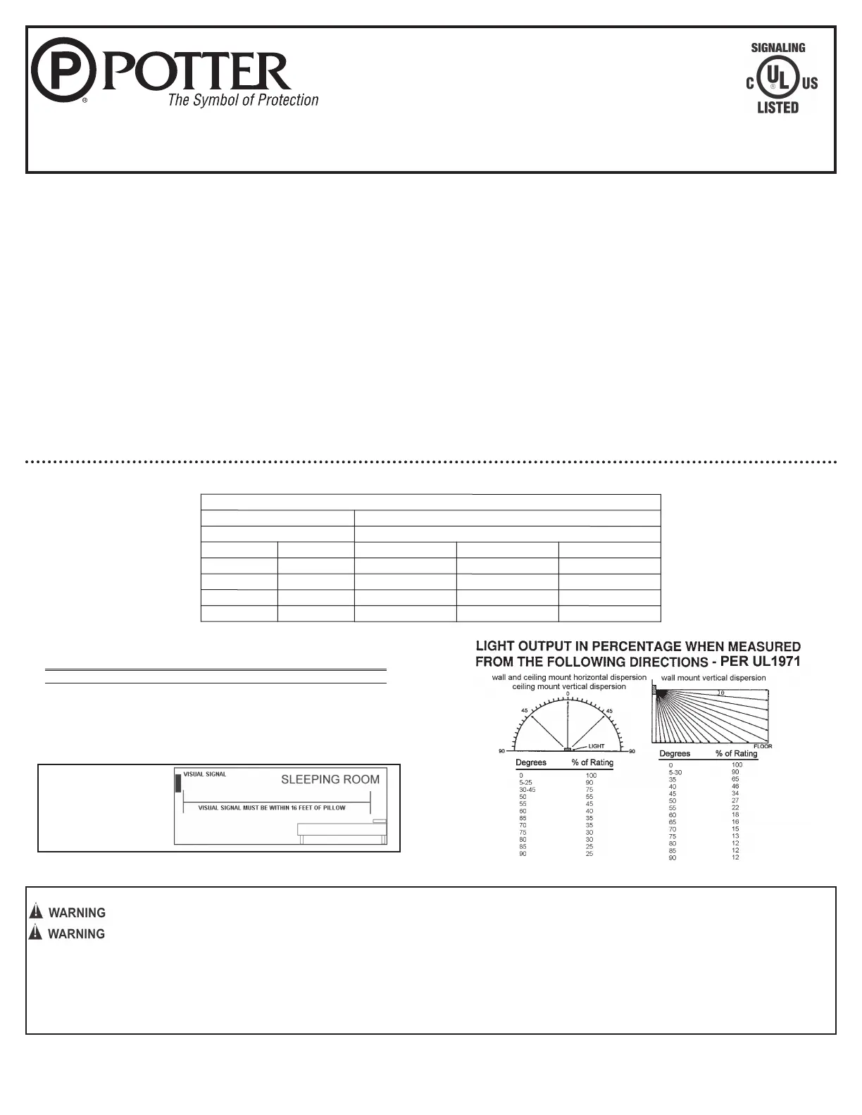
**Effective Intensity Requirements for Sleeping Area
Visible Notification Appliance
Distance from Ceiling to Top of Lens Intensity
greater than or equal to 24" (610mm) 110 Cd
less than 24" (610mm) 177 Cd
SPKSTR-
24CLP PRODUCT INFORMATION
The visual signal must be in the direct viewing area of the occupant in order to be seen.
Strobe light cannot be seen when objects such as doors, furniture or walls block strobe light.
NOTICE: VISUAL SIGNALS FOR THE HEARING IMPAIRED ARE ONLY ONE METHOD OF ALERTING THE HEARING IMPAIRED. VISUAL SIGNALS MAY NOT BE THE
PREFERRED METHOD FOR NOTIFYING ALL HEARING IMPAIRED INDIVIDUALS.
NOTICE: THE STROBE LIGHT MUST BE SEEN BY THE SLEEPING PERSON. IF THE PERSON HAS HEAD TURNED OR OTHERWISE UNABLE TO BE ALERTED BY
VISUAL, THE STROBE WILL NOT BE EFFECTIVE.
R
oom
Spaci
ng
for
C
ei
l
i
ng-
M
ounted
Vi
si
bl
e Appl
i
ances per
N
F
P
A
72,
2013
Edi
ti
on
M
i
ni
m
um
R
equi
r
ed
Li
ght
Output (
Effecti
ve
Intensi
ty
, C
d;
One Li
ght)
M
axi
m
um
R
oom
Si
ze
M
axi
m
um
C
ei
l
i
ng
H
ei
ght
M
eter
s
F
eet
10
F
oot
C
ei
l
i
ng
20
F
oot
C
ei
l
i
ng
30
F
oot
C
ei
l
i
ng
6.10
x 6.10
20
x
20
15
30
55
9.14
x 9.14
30
x
30
30
45
75
13.4
x 13.4
44
x
44
75
75
N
A
15.2
x 15.2
50
x
50
N
A
N
A
95
ADDITIONAL CAN/ULC LISTED PRODUCT INFORMATION IS FOUND ON PAGE 4
N
A
=
N
ot
al
l
ow
abl
e
UNIVERSAL MOUNT LOW PROFILE SPEAKER AND
CEILING MOUNT LOW PROFILE SPEAKER/STROBE
550-0596
Page 2
SYSTEM CONSIDERATIONS
1. To select the proper wattage input for the speaker, move the jumper to the appropriate pin.
2. Always maintain electrical isolation between speaker and strobe wiring on combination units.
3. Do not exceed 130% of rated speaker voltage. If excessive distortion is heard, check amplifier for signal clipping. If clipping exists, reduce either amplifier input or gain.
4. Four screws are provided, two for securing speaker to the back box and two for aesthetics. The two non-functional screws will be held in place by the pressure fit of the
faceplate.
IV. ELECTRICAL SPECIFICATIONS
NOTICE: DC VOLTAGE RANGE LIMITS: 16-33V. FWR VOLTAGE RANGE LIMITS: 16-33V. THIS PRODUCT WAS ONLY TESTED TO THE STATED VOLTAGE RANGE(S);
DO NOT APPLY 80% AND 110% OF THIS RANGE FOR SYSTEM OPERATION.
CLEAR Lens Strobe Current Ratings
Use with SPKSTR-24CLP Products
Candela
Regulated 24VDC
Max. Operating
Current (mA)
Regulated 24VFWR
Max. Operating
Current (mA)
15 120 190
30 120 191
75 200 277
95 220 298
115 290 418
Field Selectable Power Tap Selection - Reverberant (dBA @ 10ft.)
Voltage 1/8 Watt 1/4 Watt 1/2 Watt 1 Watt 2 Watt 4 Watt
25 Volts 74.6 dBA 77.7 dBA 80.5 dBA 83.1 dBA 85.6 dBA 87.9 dBA
70.7 Volts 73.7 dBA 76.7 dBA 79.6 dBA 82.5 dBA 85.4 dBA 87.9 dBA
Visual signal should NEVER be relied upon as the primary fire alert for the hearing impaired under these common sense conditions:
a. Sleeping face down on the bedding or pillow
b. Use of sleep medications of any kind
c. Use of alcoholic beverages or recreational drugs
d. Use of eye shades
e. If there are tendencies of deep sleep conditions
f. If a fire cuts power to AC circuits, the visual signal will not operate
g. If person is not within line of sight of visual signals
Under these and other similar common situations an alternate fire alert method such as a non-hearing impaired attendant is needed. The visual signal only
increases the chance of being alerted to the presence of fire. No system of this type can fully protect the hearing impaired in case of fire.
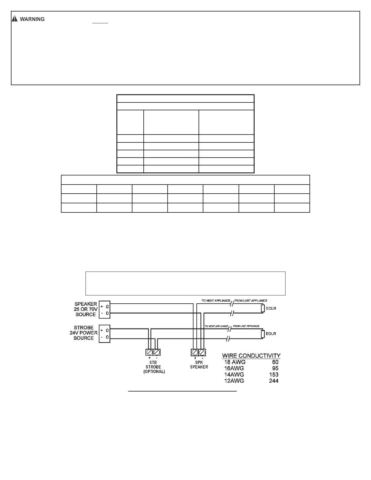
CAUTION
WHEN INSTALLING, ROUTE FIELD WIRING AWAY FROM SHARP
PROJECTIONS, CORNERS AND INTERNAL COMPONENTS.
NOTICE: DO NOT USE LOOPED
WIRE UNDER TERMINALS.
BREAK WIRE RUN TO PROVIDE
SUPERVISION OF CONNECTION.
PANEL VOLTAGE - DEVICE MINIMUM VOLTAGE
TOTAL CURRENT DRAW
* INCLUDES WIRE TO AND FROM APPLIANCE.
ASSUMES ALL APPLIANCES ARE AT THE END OF WIRE RUN (WORST CASE).
CAUTION: APPLIES ONLY TO REGULATED SUPPLIES.
*MAX. WIRE DISTANCE (IN FEET) = X WIRE CONDUCTIVITY (STROBE ONLY)
NOTICE: ALL STROBES ARE DESIGNED TO FLASH AS SPECIFIED WITH CONTINUOUS APPLIED VOLTAGE. THIS APPLIANCE IS NOT RECOMMENDED FOR USE ON CODED OR
PULSING SIGNALING CIRCUITS. HOWEVER, USE OF THE AVSM CONTROL MODULE IS PERMITTED TO SYNCHRONIZE THE STROBE.
NOTICE: REFERENCE AVSM CONTROL MODULE MANUAL (550-0598, DATED 2-1-13) FOR SYNCHRONIZATION MODULE WIRING DIAGRAMS. AVSM MANUAL CAN BE OBTAINED BY
CALLING POTTER ELECTRIC SIGNAL COMPANY AT 1-800-325-3936.

550-0596
Page 3
V
. MOUNTING ROUGH-IN BOX AND RUN WIRING
MOUNTING - SPEAKER
TO SPKRBB BACK BOX
WALL OR CEILING MOUNT
MOUNTING - SPEAKER/STROBE
To 4” Square x 2 1/8” Deep
METALLIC BACK BOX - CEILING MOUNT
SPKSTR-24CLP FIELD SELECTABLE CANDELA SELECTOR
Adjust intensity by inserting small flat blade
screwdriver to turn dial. Displayed number will
indicate selected candela.
NOTICE: FIELD SELECTABLE OPTIONS OF 15, 30,
75, 95 AND 115 CANDELA.
Adjust power taps using
needle nose pliers.
THIS APPLIANCE WILL NOT OPERATE WITHOUT ELECTRICAL POWER. AS FIRES FREQUENTLY CAUSE POWER INTERRUPTIONS,
POTTER ELECTRIC SUGGESTS YOU DISCUSS FURTHER SAFEGUARDS WITH YOUR LOCAL FIRE PROTECTION SPECIALIST.
VI. CHECKOUT AND TROUBLESHOOTING
1. Supply power to the system control panel. The auxiliary signaling device should not be activated.
2. If the signal is activated:
a. Check all smoke and fire detectors in the system to make sure they have not been activated.
b. Check all wiring connections to make sure the signal detection circuits are not reversed or shorted together. Check wire color codes and traces.
3. To test the FASPKR and SPKSTR-24CLP Series and other signaling appliances, trip the auxiliary panel, activate alarm circuit at the main control panel or activate one of
the fire detection units in the system. All auxiliary signals should be activated.
4. An operational test on this product should be conducted in accordance with National Standards or at a minimum annually and more often if dictated by local and state
codes or authorities having jurisdiction.
SIGNALING APPLIANCE LIMITATIONS:
Your speaker meets or exceeds current audibility requirements of ANSI/UL 1480. However, if the appliance is located outside a bedroom it may not wake up a sound
sleeper, especially if the room door is closed or only partially open.
Product Specifications
| Brand: | Potter |
| Category: | Speaker |
| Model: | FASPKR |
Do you need help?
If you need help with Potter FASPKR, ask a question below and other users will answer you
Speaker Potter User Manuals

20 October 2024
Speaker User Manuals
- Speaker Sony
- Speaker Xiaomi
- Speaker LG
- Speaker Bosch
- Speaker IKEA
- Speaker HP
- Speaker Philips
- Speaker Panasonic
- Speaker Hama
- Speaker Vorago
- Speaker Jensen
- Speaker Avantree
- Speaker Edifier
- Speaker Reflexion
- Speaker Meridian
- Speaker Teufel
- Speaker Kogan
- Speaker Soundcore
- Speaker Turbosound
- Speaker GoGEN
- Speaker Pro-Ject
- Speaker Yamaha
- Speaker Morel
- Speaker Axis
- Speaker Extron
- Speaker Media-tech
- Speaker Pioneer
- Speaker EarFun
- Speaker Ecler
- Speaker Audac
- Speaker Woxter
- Speaker KEF
- Speaker Audio-Technica
- Speaker Toa
- Speaker Metra
- Speaker Pyle
- Speaker Sencor
- Speaker Bose
- Speaker Orava
- Speaker Grundig
- Speaker JVC
- Speaker Kicker
- Speaker Auna
- Speaker Midland
- Speaker OSD Audio
- Speaker Power Dynamics
- Speaker Fenton
- Speaker Vonyx
- Speaker Bluesound
- Speaker Hertz
- Speaker Kenwood
- Speaker MB Quart
- Speaker Bigben
- Speaker Aplic
- Speaker CSL
- Speaker Bearware
- Speaker NUVO
- Speaker Maginon
- Speaker Infiniton
- Speaker Roku
- Speaker GPO
- Speaker Advance
- Speaker Sonance
- Speaker AXESS
- Speaker Be Cool
- Speaker Artsound
- Speaker Denon
- Speaker Ion
- Speaker Marshall
- Speaker Yorkville
- Speaker V-Tac
- Speaker MyDJ
- Speaker Valcom
- Speaker Celly
- Speaker JBL
- Speaker Infinity
- Speaker Majority
- Speaker Nedis
- Speaker Sharp
- Speaker Helix
- Speaker Genesis
- Speaker Klipsch
- Speaker Worx
- Speaker Muse
- Speaker Ground Zero
- Speaker Karma
- Speaker Glemm
- Speaker Match
- Speaker Speed-Link
- Speaker Renkforce
- Speaker Definitive Technology
- Speaker QSC
- Speaker WHD
- Speaker Q Acoustics
- Speaker Karcher
- Speaker GoldenEar
- Speaker Pyramid
- Speaker FoneStar
- Speaker Trevi
- Speaker Monitor Audio
- Speaker Canton
- Speaker Fresh N Rebel
- Speaker Energy Sistem
- Speaker Bauhn
- Speaker PSB
- Speaker Vizio
- Speaker Polk
- Speaker ESX
- Speaker Omnitronic
- Speaker MEE Audio
- Speaker Monacor
- Speaker ModeCom
- Speaker Hercules
- Speaker Black Hydra
- Speaker Electro-Voice
- Speaker Wharfedale
- Speaker Boss
- Speaker Tannoy
- Speaker Mount-It!
- Speaker GMB Audio
- Speaker Mad Dog
- Speaker Ashly
- Speaker Memphis Audio
- Speaker Focal
- Speaker Alpine
- Speaker ATen
- Speaker Genelec
- Speaker Bazooka
- Speaker Lamax
- Speaker NGS
- Speaker Aiaiai
- Speaker RCF
- Speaker SVS
- Speaker Aiwa
- Speaker N-Gear
- Speaker Atlas
- Speaker PowerBass
- Speaker Prime3
- Speaker Harman Kardon
- Speaker Lexibook
- Speaker Ibiza Sound
- Speaker Creative
- Speaker Aconatic
- Speaker DAP Audio
- Speaker REL Acoustics
- Speaker Sonus Faber
- Speaker Xcellon
- Speaker OWI
- Speaker Titanwolf
- Speaker Weather X
- Speaker HK Audio
- Speaker Phoenix Gold
- Speaker Krüger And Matz
- Speaker Indiana Line
- Speaker Blue Tees
- Speaker BASSBOSS
- Speaker Polsen
- Speaker Deaf Bonce
- Speaker Tangent
- Speaker FBT
- Speaker Transparent
- Speaker IHome
- Speaker Martin Logan
- Speaker Andover
- Speaker ILive
- Speaker Moonki
- Speaker BlueAnt
- Speaker HuddleCamHD
- Speaker X JUMP
- Speaker PulseAudio
- Speaker Urban Revolt
- Speaker Audison
- Speaker Boynq
- Speaker Dynaudio
- Speaker Clarity
- Speaker VIETA PRO
- Speaker Sonoro
- Speaker Yamazen
- Speaker OTTO
- Speaker Soen
- Speaker Miller & Kreisel
- Speaker Qian
- Speaker Iriver
- Speaker Standard Horizon
- Speaker The Box
- Speaker August
Latest Speaker User Manuals
27 October 2024
27 October 2024
27 October 2024
27 October 2024
27 October 2024
27 October 2024
27 October 2024
27 October 2024
27 October 2024
27 October 2024