Tektronix P6316 Manual
Tektronix
Not categorized
P6316
Read below 📖 the manual in Italian for Tektronix P6316 (6 pages) in the Not categorized category. This guide has been helpful for 13 people and has been rated 4.5 stars on average by 2 users
Page 1/6

xx
Product Description
The P6316 digital probe connects the Tektronix MSO2000
Series of mixed-signal oscilloscopes to digital buses and signals
on your target system. The probe breaks out 16 data channels
over two 2x8-pin headers (GROUP 1 and GROUP 2). Each
header includes eight signals on one row and eight grounds
along the opposite row.
A pair of interchangable flying lead sets are included with the
probe. The lead sets bring out one ground connectio
n on each
end and eight signal leads for connecting to individual test
points.
Connecting the Probe to the Oscilloscope
Connect the probe as shown in the illustration below.
1. Insert the probe label-side up into the receptacle.
2. To remove the probe, squeeze the buttons on the side and
pull out the probe.
Connecting the Probe to Your Circuit
Attach the probe to the circuit using the connectors and adapters
shown on the back of these instructions. Select the best method
for your needs, and then proceed to Setting up the Probe.
Setting up the Probe
Press the D15-D0 button to set and view the following
parameters of each digital channel:
Threshold voltage and vertical position
Signal height (set once for all 16 channels)
Channel label
The default settings are 1.4 V thresholds with no channel labels.
Use the B1 and B2 buttons to set and view bus characteristics
such as:
Clock type
Bus type (Serial or Parallel)
Bus width
Display format (Hex, Binary, ASCII)
Parallel bus setup information is resident on the MSO Family
of oscilloscopes. However, for other buses such as CAN and
I2C, you must have the appropriate application key. See your
oscilloscope manual or product data sheet for nomenclature
and ordering details.
Functional Check
Logic activity immediately displays on all connected, active
channels. If you do not see an active signal:
1. Press Trigger.
2. Select Edge for trigger type.
3. Select the channel that you are setting up as the source.
4. Press Aut
oset.
If you do not see an active signal, try another probe channel (or
analog probe) to verify circuit activity at the test point.
Specifications
Table 1: Electrical and mechanical specifications
Characteristic Description
Input channels 16
Threshold voltage range ±20 V
Threshold accuracy
±100 mV + 3% of threshold setting
Minimu
m signal swing
500 mV p
-p
Maximum signal swing ±20 V centered around the
threshold voltage
Maximum nondestructive
input signal to probe
±40 V p-p
Input resistance
101 kΩ
Input capacitance 8.0 pF
Minimum detectable input
pulse
5 ns
Probe length
0.9 m (3 ft)
Table 2: Environmental specifications
Characteristics Description
Temperature
Maximum operating
Minimum operating
Nonoperating
+50 °C (+122 °F)
0 °C (+32 °F)
–40 °C to +71 °C
(–40 °F to +160 °F)
Humidity
5% to 95% relative humidity at up
to +30 °C (+86 °F)
5% to 60% RH above +30° C
(+86
°F) up to +50 °C (+122 °F),
non-condensing
Altitude
Oper
ating
Nonoperating
3 km (9,843 ft) maximum
12 km
(39,370 ft) maximum
Electrostatic Immunity The probe is not static sensitive
Equipment Recycling. This product complies
with the European Union’s requirements according
to Directive 2002/96/EC on waste electrical
and
electronic equipment (WEEE). For more
information about recycling options, check the
Support/Service section of the Tektronix Web site
(www.tektronix.com).
Safety Summary
Connect and Disconnect Properly. Connect the probe output
to the measurement instrument before connecting the probe
to the circuit under test. Disconnect the probe input and the
probe ground from the circuit under test before disconnecting
the probe from the measurement instrument.
Observe All Terminal Ratings. To avoid fire or shock hazard,
observe all ratings and markings on the product. Consult the
product manual for further ratings information before making
connections to the product.
Do not Operate Without Covers. Do not touch exposed
connections and components when power is present.
Avoid Exposed Circuitry. Do not touch exposed connections
and components when power is present.
Do Not Operate With Suspected Failures. If you suspect there is
damage to this product, have it inspected by qualified service
personnel.
Do Not Operate in Wet/Damp Conditions. Do Not Operate in an
Explosive Atmosphere.
Keep Product Surfaces Clean and Dry.
Safety Terms and Symbols Terms in This Manual.
These terms may appear in this manual:
WARNING. Warning statements identify conditions or
practices that could result in injury or loss of life.
CAUTION. Caution statements identify conditions or
practices that could result in damage to this product or
other property.
Symbols on the Product. These symbols may appear on the
product:
Typical Application
1. Use the P6316 probe to view digital signals on a system
bus.
2. Use analog probes, such as the P6139A or P2221 probes
to view analog waveform information.
P6316
Digital Probe
Instruct
ions
x
1
*P0712
34500*
071-2345-00
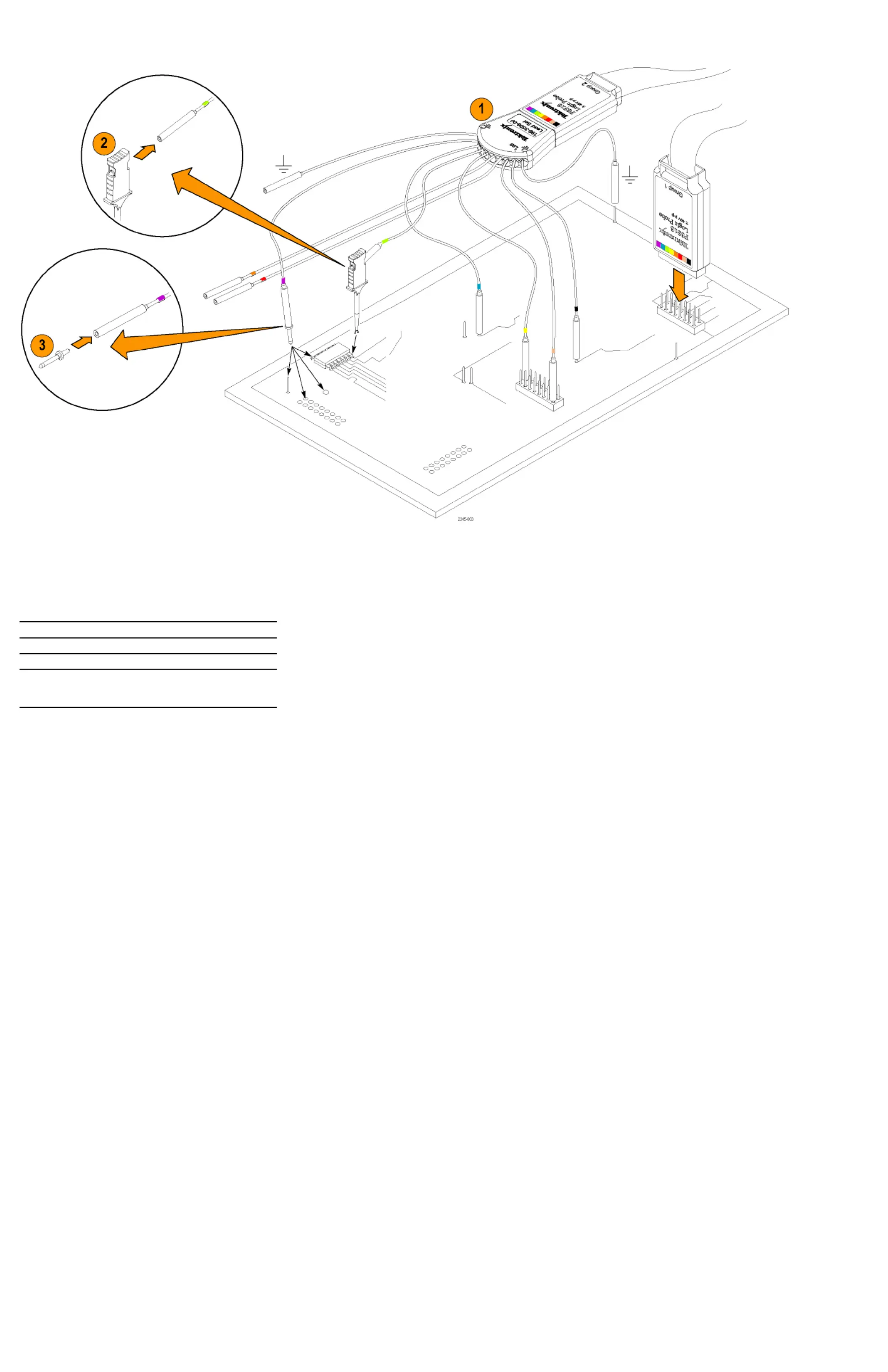
Connecting the Probe to the Circuit
Standard Accessories
The following standard accessories ship with the probe and are
shown in the illustration above.
Item
number Description Quantity
Part
number
1
8-Channel leadset
2 ea 196-3508-XX
2 Micro grabber clip
2 kits of 10 ea
020-2896-XX
3 Probe tip
2 kits of 5 ea
020-2897-XX
Instructions (English,
Japanese, & Simplified
Chinese languages)
1 ea 071-2345-XX
Contacting Tektronix
Web sit
e:
www.te
ktronix.com
Phone: 1-800-833-9200
Address: Tektronix, Inc.
Department or name (if known)
14200 SW Karl Braun
Drive P.O. Box 500
Beave
rton, OR 97077
USA
Email:
techsupport@tektronix.com
Warra
nty Information
For warranty information, go to www.tektronix.com/warranty
Copyright © Tektronix, Inc. All rights reserved. www.tektronix.com

xx
製品の説明
製品の説明
製品の説明
製品の説明製品の説明
P6316 型デジタル・プローブは、当社MSO2000 シリーズ・ミッ
クスドシグナル・オシロスコープをターゲット・システムのデジタ
ル・バスおよび信号に接続するのに使用します。2 つの 2×8
ピン・ヘッダ(グループ 1 および グループ 2)を持ち、合計16
のデータ・チャンネルを測定できます。どちらのヘッダも、8 つ
の信号が 1 列に配置され、それと対を成す形で 8 つの GND
がもう 1 列に配置されています。
相互に交換可能なフライング・リード・セットが一対付属して
います。これらのリード・セットでは、両エンドに GND を各 1
本接続し、8 本の信号リードを個々の測定ポイントに接続し
ます。
プローブをオシロスコープに接続
プローブをオシロスコープに接続
プローブをオシロスコープに接続
プローブをオシロスコープに接続プローブをオシロスコープに接続
以下の図に示すようにプローブを接続します。
1.
1.
1.
1.1. ラベル面を上にしてプローブをレセプタクルに挿入しま
す。
2.
2.
2.
2.2. プロー
ブを取り外すには、両サイドのボタンを押してプ
ローブを引き抜きます。
プローブを回路に接続
プローブを回路に接続
プローブを回路に接続
プローブを回路に接続プローブを回路に接続
プローブを回路に接続するには、コネクタとアダプタ(裏面
に記載)を使用します。ニーズに最も合う方法を選択し、「プ
ローブのセットアップ」の指示に従います。
プローブのセットアップ
プローブのセットアップ
プローブのセットアップ
プローブのセットアッププローブのセットアップ
D15-D0 ボタンを押して、各デジタル・チャンネルの以下のパ
ラメータを設定および表示します。
スレッショルド電圧と垂直位置
信号高さ(個別に全 16 チャンネルを設定)
チャンネル・ラベル
デフォルト設定は、スレッショルド電圧1.4 V、チャンネル・ラ
ベルなし。
以下のバス特性の設定と表示には、B1 ボタンと B2 ボタンを
使用します。
クロックの種類
バスの種類(シリアルまたはパラレル)
バス幅
表示形式(16 進、2 進、ASCII)
パラレル・バスのセットアップ情報は、MSO ファミリのオシロ
スコープに格納されています。しかし、その他のバス(CAN、
I2C など)については、所定のアプリケーション・キーが必要
です。名称と発注情報については、ご使用のオシロスコープ
のマニュアルまたは製品データ・シートを参照してください。
機能チェック
機能チェック
機能チェック
機能チェック機能チェック
接続されたすべてのアクティブなチャンネルについて、ロジッ
ク・アクティビティが直ちに表示されます。アクティブな信号が
表示されない場合は、次の操作を実行してください。
1.
1.
1.
1.1. Trigger を押します
。
2.
2.
2.
2.2. トリガのタイプとして、Edge を選択します。
3.
3.
3.
3.3. ソースとしてセットアップするチャンネルを選択します。
4.
4.
4.
4.4. Autoset を押します。
アクティブな信号が表示されない場合は、他のプローブ・チャ
ンネル(またはアナログ・プローブ)を使用して、測定ポイント
における回路のアクティビティを検証してください。
仕様
仕様
仕様
仕様仕様
表
表
表
表表 1
1
1
11:
:
:
:: 電気仕様と機械仕様
電気仕様と機械仕様
電気仕様と機械仕様
電気仕様と機械仕様電気仕様と機械仕様
特性
特性
特性
特性特性説明
説明
説明
説明説明
入力チャンネル
16
スレッショルド電圧の範囲
±20 V
スレッショルドの確度
±100 mV + スレッショルド設定
の 3%
最小信号スイング
500 mV p-p
最大信号スイング
スレッショルド電圧 ±20 V
プローブへの最大非破壊
入力信号
±40 V p-p
入力抵抗
101 kΩ
入力キャパシタンス
8.0 pF
検出可能最小入力パルス
5 ns
プローブ長
0.9 m(3 フィート)
表
表
表
表表 2
2
2
22:
:
:
:: 環境仕様
環境仕様
環境仕様
環境仕様環境仕様
特性
特性
特性
特性特性説明
説明
説明
説明説明
温度
動作時最高温度
動作時最低温度
非動作時
+50 ℃(+122 °F)
0 ℃(+32 °F)
–40 ℃ ~+71 ℃
(–40 °F ~+160 °F)
湿度
+30 ℃(+86 °F)以下で 5% ~
95% の相対湿度
+30 ℃ (+86 °F ) ~ +50 ℃
(+
122 °F)、結露のない状態
で、5% ~60% の相対湿度
高度
動作時
非動作時
最高 3 km(9,843 フィート)
最高 12 km(39,370 フィート)
静電気イミュニティ
このプローブは静電気に対する
耐
性があります。
機器のリサイクル
機器のリサイクル
機器のリサイクル
機器のリサイクル機器のリサイクル:
:
:
:: 本製品は WEEE Directive
2002/96/EC (廃棄電気・電子機器に関する指
令)に基づく EU の諸要件に準拠しています。リ
サイクル方法の詳細につ
いては、当社Web サ
イト(www.tektronix.com)の「Support/Service」を
参照してください。
安全にご使用いただくために
安全にご使用いただくために
安全にご使用いただくために
安全にご使用いただくために安全にご使用いただくために
接続と切断は正しく行ってく
接続と切断は正しく行ってく
接続と切断は正しく行ってく
接続と切断は正しく行ってく接続と切断は正しく行ってください
ださい
ださい
ださいださい。
。
。
。。:
:
:
:: 測定対象の回路にプ
ローブを接続する前に、プローブの出力を計測機器に接続
してください。計測機器からプローブを外す前に、測定対象
の回路からプローブの入力と GND を外してください。
すべての端子の定格に従ってください
すべての端子の定格に従ってください
すべての端子の定格に従ってください
すべての端子の定格に従ってくださいすべての端子の定格に従ってください。
。
。
。。:
:
:
:: 出火や感電の危
険を避けるために、本製品のすべての定格とマークの意味
をご確認ください。本製品を接続する前に、製品マニュアル
を参照してその他の定格情報をご確認ください。
カバーを外した状態では使用しないでください
カバーを外した状態では使用しないでください
カバーを外した状態では使用しないでください
カバーを外した状態では使用しないでくださいカバーを外した状態では使用しないでください。
。
。
。。:
:
:
:: 電源がオ
ンのときに、露出した接地部分やコンポーネントに触れない
でください。
回路の露出を避けてください
回路の露出を避けてください
回路の露出を避けてください
回路の露出を避けてください回路の露出を避けてください。
。
。
。。:
:
:
:: 電源がオンのときに、露出
した接地部分やコンポーネントに触れないでください。
故障の疑いがあるときは使
故障の疑いがあるときは使
故障の疑いがあるときは使
故障の疑いがあるときは使故障の疑いがあるときは使用しないでください
用しないでください
用しないでください
用しないでください用しないでください。
。
。
。。:
:
:
:: 本製品に
損傷の疑いがある場合、資格を有するサービス担当者に点
検をご依頼ください。
湿気の多いところでは使用しないでください
湿気の多いところでは使用しないでください
湿気の多いところでは使用しないでください
湿気の多いところでは使用しないでください湿気の多いところでは使用しないでください。
。
。
。。:
:
:
:: 爆発性雰囲
気中では使用しないでください。
製品の表面を清潔で乾燥した状態に保ってください
製品の表面を清潔で乾燥した状態に保ってください
製品の表面を清潔で乾燥した状態に保ってください
製品の表面を清潔で乾燥した状態に保ってください製品の表面を清潔で乾燥した状態に保ってください。
。
。
。。:
:
:
::
安全に関する用語と記号
安全に関する用語と記号
安全に関する用語と記号
安全に関する用語と記号安全に関する用語と記号
このマニュアルでは次の用語を使用します。
警告
警告
警告
警告警告:
:
:
:: 「警告」は、負傷や死亡事故を招く恐れのある状
態や行為を示します。
注意
注意
注意
注意注意:
:
:
:: 「注意」は、本製品やその他の施設や機材に損害
を与える恐れのある状態や行為を示します。
本製品の記号:
本製品の記号:
本製品の記号:
本製品の記号:本製品の記号: 本製品は以下の記号に注意してご使用くだ
さい。
代表的用途
代表的用途
代表的用途
代表的用途代表的用途
1.
1.
1.
1.1. P6316 型プローブは、システム・バスのデジタル信号の
観測に使用します。
2.
2.
2.
2.2. P6139A 型または P2221 型などのアナログ・プローブは、
アナログ波形情報の観測に使用します。
P6316 型
型
型
型型
デジタル・プローブ
デジタル・プローブ
デジタル・プローブ
デジタル・プローブデジタル・プローブ
手順
手順
手順
手順手順
x
2
071-23
45-00
Product Specifications
| Brand: | Tektronix |
| Category: | Not categorized |
| Model: | P6316 |
Do you need help?
If you need help with Tektronix P6316, ask a question below and other users will answer you
Not categorized Tektronix User Manuals

14 October 2024
14 October 2024
Not categorized User Manuals
- Not categorized Candy
- Not categorized Sony
- Not categorized Electrolux
- Not categorized Samsung
- Not categorized Xiaomi
- Not categorized Casio
- Not categorized LG
- Not categorized Bosch
- Not categorized AEG
- Not categorized IKEA
- Not categorized Huawei
- Not categorized Braun
- Not categorized Brondi
- Not categorized HP
- Not categorized Philips
- Not categorized Panasonic
- Not categorized Bauknecht
- Not categorized BEKO
- Not categorized Delonghi
- Not categorized Daewoo
- Not categorized DeWalt
- Not categorized Epson
- Not categorized Etna
- Not categorized Teka
- Not categorized Apc
- Not categorized Balay
- Not categorized Siemens
- Not categorized Hama
- Not categorized Petsafe
- Not categorized Vorago
- Not categorized Neewer
- Not categorized Danby
- Not categorized Bartscher
- Not categorized Hartke
- Not categorized Bertazzoni
- Not categorized Gigabyte
- Not categorized Smeg
- Not categorized Hisense
- Not categorized Gree
- Not categorized Hoover
- Not categorized EBERLE
- Not categorized Hazet
- Not categorized Fluke
- Not categorized Goobay
- Not categorized Topeak
- Not categorized Antari
- Not categorized Thermex
- Not categorized TCL
- Not categorized Russell Hobbs
- Not categorized Panduit
- Not categorized IFM
- Not categorized Avantree
- Not categorized Royal Catering
- Not categorized Hotpoint
- Not categorized Whirlpool
- Not categorized Schwaiger
- Not categorized Nabo
- Not categorized Arendo
- Not categorized Megger
- Not categorized Balam Rush
- Not categorized Noxon
- Not categorized Sanus
- Not categorized Adidas
- Not categorized Domo
- Not categorized Cayin
- Not categorized Reflexion
- Not categorized TP Link
- Not categorized Inventum
- Not categorized Totolink
- Not categorized Shokz
- Not categorized Gamma
- Not categorized Artusi
- Not categorized Medel
- Not categorized Meris
- Not categorized D-Link
- Not categorized Navitel
- Not categorized Meridian
- Not categorized AeroCool
- Not categorized Kugoo
- Not categorized Rikon
- Not categorized Neff
- Not categorized Garmin
- Not categorized Razer
- Not categorized Teufel
- Not categorized Enermax
- Not categorized Noveen
- Not categorized StarTech.com
- Not categorized Origin Storage
- Not categorized Outwell
- Not categorized Best
- Not categorized Stihl
- Not categorized Kostal
- Not categorized ZOTAC
- Not categorized Comfee
- Not categorized Imarflex
- Not categorized Edgestar
- Not categorized Audient
- Not categorized Kogan
- Not categorized Solis
- Not categorized DJI
- Not categorized Snom
- Not categorized McIntosh
- Not categorized One For All
- Not categorized Caple
- Not categorized SereneLife
- Not categorized Roesle
- Not categorized APSystems
- Not categorized GoGEN
- Not categorized Festo
- Not categorized Create
- Not categorized Furrion
- Not categorized Oreg
- Not categorized Glorious
- Not categorized Pro-Ject
- Not categorized Yamaha
- Not categorized CaviLock
- Not categorized OOONO
- Not categorized Venom
- Not categorized Kichler
- Not categorized SMART Technologies
- Not categorized Neo
- Not categorized Newstar
- Not categorized Legrand
- Not categorized Integral LED
- Not categorized Goodram
- Not categorized Goldtouch
- Not categorized Lutec
- Not categorized Vello
- Not categorized Asus
- Not categorized Cudy
- Not categorized Hayter
- Not categorized BlueBuilt
- Not categorized Eufy
- Not categorized Gys
- Not categorized Conair
- Not categorized Turmix
- Not categorized Franke
- Not categorized Husqvarna
- Not categorized Sauber
- Not categorized Shimano
- Not categorized Axis
- Not categorized Tamron
- Not categorized Liebherr
- Not categorized Carson
- Not categorized Gourmetmaxx
- Not categorized Truelife
- Not categorized Busch-Jaeger
- Not categorized ETA
- Not categorized Voltcraft
- Not categorized Axor
- Not categorized Karran
- Not categorized Elkay
- Not categorized Varaluz
- Not categorized Extron
- Not categorized Lindy
- Not categorized Aputure
- Not categorized Netgear
- Not categorized Honor
- Not categorized XP-PEN
- Not categorized Danfoss
- Not categorized Riccar
- Not categorized Orbegozo
- Not categorized Media-tech
- Not categorized Kuppersbusch
- Not categorized Mebby
- Not categorized Pioneer
- Not categorized TONI&GUY
- Not categorized Summit
- Not categorized Accucold
- Not categorized EarFun
- Not categorized Toolcraft
- Not categorized Gram
- Not categorized Lorex
- Not categorized Catit
- Not categorized NuPrime
- Not categorized Ecler
- Not categorized Roccat
- Not categorized AudioControl
- Not categorized Elsner
- Not categorized Kask
- Not categorized Digitus
- Not categorized Cabasse
- Not categorized Koenic
- Not categorized Haier
- Not categorized Beaphar
- Not categorized Sure Petcare
- Not categorized Livall
- Not categorized Monogram
- Not categorized Sortimo
- Not categorized Unicol
- Not categorized Audio-Technica
- Not categorized Lian Li
- Not categorized JLab
- Not categorized Toa
- Not categorized Marantz
- Not categorized Knog
- Not categorized Rega
- Not categorized Vox
- Not categorized Mars Gaming
- Not categorized Kerbl
- Not categorized Metra
- Not categorized Pyle
- Not categorized Sencor
- Not categorized Hobby
- Not categorized Lenovo
- Not categorized Noctua
- Not categorized Klein Tools
- Not categorized LevelOne
- Not categorized Shure
- Not categorized Michael Todd Beauty
- Not categorized GRAUGEAR
- Not categorized Trixie
- Not categorized Schneider
- Not categorized Lorelli
- Not categorized Roland
- Not categorized OBSBOT
- Not categorized SuperTooth
- Not categorized Kluge
- Not categorized Bobrick
- Not categorized Signature Hardware
- Not categorized Martin
- Not categorized Kanto
- Not categorized Scott
- Not categorized Delta
- Not categorized Kindermann
- Not categorized Robern
- Not categorized Hortus
- Not categorized DeLock
- Not categorized Coyote
- Not categorized Kidde
- Not categorized Anker
- Not categorized Growatt
- Not categorized Nanoleaf
- Not categorized Grundig
- Not categorized Mistral
- Not categorized VMV
- Not categorized S.M.S.L
- Not categorized Privileg
- Not categorized MPM
- Not categorized PeakTech
- Not categorized Niceboy
- Not categorized Engenius
- Not categorized Khind
- Not categorized Amana
- Not categorized EMOS
- Not categorized CyberPower
- Not categorized KitchenAid
- Not categorized RGBlink
- Not categorized Clean Air Optima
- Not categorized Manfrotto
- Not categorized Exquisit
- Not categorized Cosatto
- Not categorized Fluval
- Not categorized Kicker
- Not categorized Gude
- Not categorized Auna
- Not categorized Taurus
- Not categorized Heatit
- Not categorized Midland
- Not categorized Field Optics
- Not categorized Zebra
- Not categorized Yealink
- Not categorized FIMI
- Not categorized Optex
- Not categorized Frigidaire
- Not categorized Levoit
- Not categorized Maytag
- Not categorized Deye
- Not categorized Nibe
- Not categorized Ryobi
- Not categorized Dremel
- Not categorized Breville
- Not categorized Kodak
- Not categorized Velleman
- Not categorized Sharkoon
- Not categorized RIDGID
- Not categorized Laserliner
- Not categorized Segway
- Not categorized Power Dynamics
- Not categorized DataVideo
- Not categorized RGV
- Not categorized Hendi
- Not categorized Gamdias
- Not categorized Concept
- Not categorized BeamZ
- Not categorized Livoo
- Not categorized Nexa
- Not categorized Guzzanti
- Not categorized XO
- Not categorized Steinel
- Not categorized Bluesound
- Not categorized Flex
- Not categorized Chauvin Arnoux
- Not categorized Blackstar
- Not categorized Caso
- Not categorized Kenwood
- Not categorized Cambridge
- Not categorized Nobo
- Not categorized Dell
- Not categorized Ciarra
- Not categorized Brandson
- Not categorized Mybeo
- Not categorized Aplic
- Not categorized CSL
- Not categorized Zoom
- Not categorized Tru Components
- Not categorized Bearware
- Not categorized Moen
- Not categorized Viewsonic
- Not categorized B-tech
- Not categorized IMM Photonics
- Not categorized Maginon
- Not categorized Speco Technologies
- Not categorized Nec
- Not categorized IFi Audio
- Not categorized Tripp Lite
- Not categorized Nevir
- Not categorized Infiniton
- Not categorized Ag Neovo
- Not categorized Henry Engineering
- Not categorized Taco Tuesday
- Not categorized Wire Technologies
- Not categorized GPO
- Not categorized Block
- Not categorized Maxi-Cosi
- Not categorized Ufesa
- Not categorized Milwaukee
- Not categorized Smart-AVI
- Not categorized CAME-TV
- Not categorized A-Designs
- Not categorized EchoMaster
- Not categorized Crimson
- Not categorized Elgato
- Not categorized Corsair
- Not categorized Generac
- Not categorized EVE
- Not categorized Dahua Technology
- Not categorized Cambium Networks
- Not categorized Safety 1st
- Not categorized Scarlett
- Not categorized Axxess
- Not categorized Advance
- Not categorized Indesit
- Not categorized Daikin
- Not categorized Shoprider
- Not categorized Canon
- Not categorized VAIS Technology
- Not categorized Maxsa
- Not categorized Lincoln Electric
- Not categorized BRIO
- Not categorized AXESS
- Not categorized DAB
- Not categorized Be Cool
- Not categorized Jocel
- Not categorized Bluetti
- Not categorized Blaupunkt
- Not categorized ORNO
- Not categorized Thermaltake
- Not categorized Artsound
- Not categorized Simrad
- Not categorized Volcano
- Not categorized Nordic Winter
- Not categorized TechBite
- Not categorized NEP
- Not categorized Catlink
- Not categorized Cablexpert
- Not categorized Ansmann
- Not categorized Røde
- Not categorized Makita
- Not categorized Einhell
- Not categorized Avidsen
- Not categorized Elac
- Not categorized Lewitt
- Not categorized Anova
- Not categorized Posiflex
- Not categorized Planet
- Not categorized Biostar
- Not categorized Mitsubishi
- Not categorized HeadRush
- Not categorized Showtec
- Not categorized PCE
- Not categorized Hikvision
- Not categorized Sitecom
- Not categorized Navman
- Not categorized JIMMY
- Not categorized Laica
- Not categorized Equip
- Not categorized Conceptronic
- Not categorized Sirius
- Not categorized Noyafa
- Not categorized Yorkville
- Not categorized Toro
- Not categorized Intermatic
- Not categorized Spear & Jackson
- Not categorized Tower
- Not categorized Hubble Connected
- Not categorized McGregor
- Not categorized Habitat
- Not categorized MSR
- Not categorized Entes
- Not categorized V-Tac
- Not categorized Salton
- Not categorized Novation
- Not categorized Chipolino
- Not categorized Alphatronics
- Not categorized Fezz
- Not categorized Eden
- Not categorized Fuxtec
- Not categorized Megasat
- Not categorized SolaX Power
- Not categorized Valcom
- Not categorized Mikrotik
- Not categorized Yale
- Not categorized Mosconi
- Not categorized Tristar
- Not categorized Mophie
- Not categorized Kohler
- Not categorized Envertec
- Not categorized Celly
- Not categorized Metabo
- Not categorized Jabra
- Not categorized Alphacool
- Not categorized Cuisinart
- Not categorized Doepke
- Not categorized Lupine
- Not categorized Anton/Bauer
- Not categorized Dometic
- Not categorized JBL
- Not categorized Rigol
- Not categorized Joy-it
- Not categorized Body Solid
- Not categorized DeepCool
- Not categorized Kali Audio
- Not categorized Chief
- Not categorized Majority
- Not categorized Cybex
- Not categorized Iiyama
- Not categorized Nedis
- Not categorized Sharp
- Not categorized Crock-Pot
- Not categorized Helix
- Not categorized Genesis
- Not categorized Dyson
- Not categorized Elation
- Not categorized Magmatic
- Not categorized Supermicro
- Not categorized Zendure
- Not categorized Logilink
- Not categorized Majestic
- Not categorized Basetech
- Not categorized Leviton
- Not categorized Soundstream
- Not categorized PAC
- Not categorized Xaoc
- Not categorized Eldom
- Not categorized Fisher And Paykel
- Not categorized Hohner
- Not categorized Britax
- Not categorized Elba
- Not categorized Steiner
- Not categorized Vonroc
- Not categorized Worx
- Not categorized Brentwood
- Not categorized Philco
- Not categorized Bellari
- Not categorized Rolls
- Not categorized MSI
- Not categorized Chauvet
- Not categorized Ordo
- Not categorized Ground Zero
- Not categorized OnePlus
- Not categorized V7
- Not categorized Jenn-Air
- Not categorized CRUX
- Not categorized Karma
- Not categorized Ridem
- Not categorized Glemm
- Not categorized StarIink
- Not categorized HomeCraft
- Not categorized Nostalgia
- Not categorized GameDay
- Not categorized X-Lite
- Not categorized Söll
- Not categorized Sparkle
- Not categorized Edouard Rousseau
- Not categorized Caberg
- Not categorized Exped
- Not categorized Igloo
- Not categorized Heusinkveld
- Not categorized KED
- Not categorized EPEVER
- Not categorized Grothe
- Not categorized Cane Creek
- Not categorized Swiss Eye
- Not categorized SilverStone
- Not categorized Goodis
- Not categorized TFA
- Not categorized X Rocker
- Not categorized Dreame
- Not categorized Foreo
- Not categorized Tesla
- Not categorized Aquael
- Not categorized Klarstein
- Not categorized Lauten Audio
- Not categorized Toddy
- Not categorized Lexivon
- Not categorized Icy Dock
- Not categorized Elta
- Not categorized ASI
- Not categorized Gurari
- Not categorized Varia
- Not categorized SPL
- Not categorized I-Tec
- Not categorized Xigmatek
- Not categorized Storcube
- Not categorized Tracer
- Not categorized Shark
- Not categorized REMKO
- Not categorized Phanteks
- Not categorized EnOcean
- Not categorized EK Water Blocks
- Not categorized Hoymiles
- Not categorized Envertech
- Not categorized Cougar
- Not categorized Asrock
- Not categorized Audiotec Fischer
- Not categorized Furman
- Not categorized Abac
- Not categorized Cata
- Not categorized Vivax
- Not categorized Black Diamond
- Not categorized Stanley
- Not categorized QSC
- Not categorized Bitspower
- Not categorized Black And Decker
- Not categorized Weston
- Not categorized Dobot
- Not categorized WHD
- Not categorized Schuberth
- Not categorized Q Acoustics
- Not categorized Scotsman
- Not categorized Radial Engineering
- Not categorized Karcher
- Not categorized Orion
- Not categorized A-NeuVideo
- Not categorized Beem
- Not categorized Logitech
- Not categorized Boneco
- Not categorized Atlona
- Not categorized EZ Dupe
- Not categorized Becken
- Not categorized DVDO
- Not categorized GoXtreme
- Not categorized Primacoustic
- Not categorized Avanti
- Not categorized Acros
- Not categorized Phil And Teds
- Not categorized Jotul
- Not categorized Thermarest
- Not categorized Dedra
- Not categorized Powerplus
- Not categorized Vivanco
- Not categorized TC Electronic
- Not categorized Suzuki
- Not categorized Bionaire
- Not categorized Huslog
- Not categorized Glem Gas
- Not categorized Apogee
- Not categorized Atomos
- Not categorized IOptron
- Not categorized Trevi
- Not categorized Palmer
- Not categorized R-Go Tools
- Not categorized Drayton
- Not categorized Spektrum
- Not categorized Jung
- Not categorized Götze & Jensen
- Not categorized Native Instruments
- Not categorized Homedics
- Not categorized Xvive
- Not categorized AMX
- Not categorized Perlick
- Not categorized Peavey
- Not categorized BenQ
- Not categorized Princess
- Not categorized FOX ESS
- Not categorized Waterstone
- Not categorized Mr Steam
- Not categorized Fresh N Rebel
- Not categorized DuroStar
- Not categorized Duromax
- Not categorized Owon
- Not categorized REVITIVE
- Not categorized Fosi Audio
- Not categorized Europalms
- Not categorized Sven
- Not categorized Global Water
- Not categorized Hamilton Beach
- Not categorized Extech
- Not categorized Tunturi
- Not categorized Craftsman
- Not categorized Gastronoma
- Not categorized Lumens
- Not categorized Brizo
- Not categorized Xinfrared
- Not categorized Getac
- Not categorized ProLights
- Not categorized Phonak
- Not categorized Cherub
- Not categorized Thor
- Not categorized Laurastar
- Not categorized Ambiano
- Not categorized Bissell
- Not categorized Antelope Audio
- Not categorized ESYLUX
- Not categorized Austral
- Not categorized LiveU
- Not categorized RF-Links
- Not categorized Fortinge
- Not categorized Mercury
- Not categorized Vaddio
- Not categorized InFocus
- Not categorized Stinger
- Not categorized NEXTO DI
- Not categorized Abus
- Not categorized AV Tool
- Not categorized Bauhn
- Not categorized Adventure Kings
- Not categorized EQ Acoustics
- Not categorized Michigan
- Not categorized Vent-A-Hood
- Not categorized Audix
- Not categorized Vizio
- Not categorized Livarno Lux
- Not categorized Grillmeister
- Not categorized Ernesto
- Not categorized Neno
- Not categorized Rommelsbacher
- Not categorized One Control
- Not categorized Bome
- Not categorized Redback Technologies
- Not categorized ESX
- Not categorized City Theatrical
- Not categorized Omnitronic
- Not categorized Reber
- Not categorized Kaiser Nienhaus
- Not categorized Crestron
- Not categorized Eurolite
- Not categorized Manhattan
- Not categorized Xavax
- Not categorized MOZA
- Not categorized Rocstor
- Not categorized Cruz
- Not categorized Newland
- Not categorized Edimax
- Not categorized Dragonshock
- Not categorized Russound
- Not categorized Adj
- Not categorized Olivetti
- Not categorized EVOLVEO
- Not categorized Stadler Form
- Not categorized Wolfcraft
- Not categorized Monacor
- Not categorized Heinner
- Not categorized Minolta
- Not categorized Sena
- Not categorized Innoliving
- Not categorized Aqara
- Not categorized POGS
- Not categorized Beghelli
- Not categorized BodyCraft
- Not categorized Superrollo
- Not categorized Mx Onda
- Not categorized Bixolon
- Not categorized Maruyama
- Not categorized Bravilor Bonamat
- Not categorized Hilti
- Not categorized D-Jix
- Not categorized Black Hydra
- Not categorized I.safe Mobile
- Not categorized Nimbus
- Not categorized Lowrance
- Not categorized Roxio
- Not categorized Accsoon
- Not categorized Inspire
- Not categorized Sebo
- Not categorized Boss
- Not categorized Tannoy
- Not categorized Prompter People
- Not categorized JL Audio
- Not categorized Edesa
- Not categorized IOIO
- Not categorized Genexis
- Not categorized Buzz Rack
- Not categorized ZKTeco
- Not categorized Giordani
- Not categorized Cadel
- Not categorized Dualit
- Not categorized Atlas Sound
- Not categorized Solo
- Not categorized Wagner
- Not categorized Bluestork
- Not categorized Davis
- Not categorized Comica
- Not categorized AddLiving
- Not categorized Melitta
- Not categorized Lowell
- Not categorized INOGENI
- Not categorized Nearity
- Not categorized Kiloview
- Not categorized Middle Atlantic
- Not categorized Mount-It!
- Not categorized Morley
- Not categorized Ampeg
- Not categorized Apantac
- Not categorized Carry-on
- Not categorized Liftmaster
- Not categorized GVision
- Not categorized IPGARD
- Not categorized Murideo
- Not categorized TK Audio
- Not categorized Rosco
- Not categorized Proaim
- Not categorized Cisco
- Not categorized CGV
- Not categorized Vacmaster
- Not categorized Elmo
- Not categorized Libec
- Not categorized Point Source Audio
- Not categorized Macally
- Not categorized Ade
- Not categorized MooreCo
- Not categorized Di4
- Not categorized Mellerware
- Not categorized Zenec
- Not categorized Silver Cross
- Not categorized American DJ
- Not categorized AJA
- Not categorized Postium
- Not categorized RME
- Not categorized SurgeX
- Not categorized Alcon
- Not categorized Vantec
- Not categorized Silverline
- Not categorized VAVA
- Not categorized Vicoustic
- Not categorized LERAN
- Not categorized Doffler
- Not categorized Profoto
- Not categorized TensCare
- Not categorized Scanstrut
- Not categorized Industrial Music Electronics
- Not categorized Source Audio
- Not categorized Black Lion Audio
- Not categorized Wiha
- Not categorized Puls Dimension
- Not categorized Wasp
- Not categorized Gamewright
- Not categorized ISDT
- Not categorized Ilve
- Not categorized Reolink
- Not categorized Bebob
- Not categorized Ashly
- Not categorized Claypaky
- Not categorized Premier Mounts
- Not categorized MuxLab
- Not categorized Icy Box
- Not categorized Holosun
- Not categorized Seagate
- Not categorized Holzmann
- Not categorized Blackmagic Design
- Not categorized Audiolab
- Not categorized Modbap Modular
- Not categorized Genius
- Not categorized Rommer
- Not categorized Traeger
- Not categorized Memphis Audio
- Not categorized Focal
- Not categorized Belkin
- Not categorized BDI
- Not categorized Alpine
- Not categorized Ring
- Not categorized TomTom
- Not categorized XGIMI
- Not categorized Omron
- Not categorized Starlink
- Not categorized Celestron
- Not categorized Gymform
- Not categorized Glide Gear
- Not categorized Oppo
- Not categorized Chicco
- Not categorized AVM
- Not categorized Impact
- Not categorized Pelco
- Not categorized FoxFury
- Not categorized Mammut
- Not categorized Heritage Audio
- Not categorized Safco
- Not categorized Monoprice
- Not categorized Stabila
- Not categorized CTA Digital
- Not categorized Olight
- Not categorized Primo
- Not categorized HammerSmith
- Not categorized Cyrus
- Not categorized Roadinger
- Not categorized Steelbody
- Not categorized Ventev
- Not categorized Elektrobock
- Not categorized Triton
- Not categorized Trisa
- Not categorized Corberó
- Not categorized Korg
- Not categorized Atosa
- Not categorized STANDIVARIUS
- Not categorized Avteq
- Not categorized Izzy
- Not categorized PureLink
- Not categorized UNYKAch
- Not categorized Al-ko
- Not categorized ADATA
- Not categorized Mobotix
- Not categorized Kramer
- Not categorized ATen
- Not categorized Blustream
- Not categorized Laserworld
- Not categorized Kunft
- Not categorized Milesight
- Not categorized Spanninga
- Not categorized Bialetti
- Not categorized Xlyne
- Not categorized Plant Craft
- Not categorized Sungrow
- Not categorized Grundfos
- Not categorized Bazooka
- Not categorized Carlsbro
- Not categorized MoFi
- Not categorized Blackburn
- Not categorized Bang And Olufsen
- Not categorized Sole Fitness
- Not categorized Cowon
- Not categorized Bebe Confort
- Not categorized WHALE
- Not categorized Stalco
- Not categorized Horizon Fitness
- Not categorized Sonel
- Not categorized Jilong
- Not categorized Tenda
- Not categorized Maytronics
- Not categorized Tempmate
- Not categorized Idec
- Not categorized Analog Way
- Not categorized Gamesir
- Not categorized ZyXEL
- Not categorized Vogue
- Not categorized Frilec
- Not categorized Yaesu
- Not categorized Concept2
- Not categorized Musical Fidelity
- Not categorized Flir
- Not categorized Rademacher
- Not categorized NGS
- Not categorized CTOUCH
- Not categorized RCF
- Not categorized Microchip
- Not categorized Homematic IP
- Not categorized WilTec
- Not categorized Thomson
- Not categorized Easypix
- Not categorized LC-Power
- Not categorized SVS
- Not categorized 8BitDo
- Not categorized Pardini
- Not categorized Audeze
- Not categorized Everdure
- Not categorized Insta360
- Not categorized Fieldmann
- Not categorized Alpen Kreuzer
- Not categorized Xplora
- Not categorized H.Koenig
- Not categorized Aiwa
- Not categorized Wimberley
- Not categorized Insignia
- Not categorized Playtive
- Not categorized Vimar
- Not categorized Osprey
- Not categorized Hosa
- Not categorized Havis
- Not categorized Emerson
- Not categorized Weasy
- Not categorized Biltema
- Not categorized Bogen
- Not categorized Electro Harmonix
- Not categorized Vocopro
- Not categorized Chrome-Q
- Not categorized Galaxy Audio
- Not categorized Altman
- Not categorized Aiphone
- Not categorized Atlas
- Not categorized Graco
- Not categorized Manta
- Not categorized MARTOR
- Not categorized Mean Well
- Not categorized HMS Premium
- Not categorized Exelpet
- Not categorized Trendnet
- Not categorized G-Technology
- Not categorized CubuSynth
- Not categorized Simpson
- Not categorized Infasecure
- Not categorized SecureSafe
- Not categorized Intellinet
- Not categorized Hikoki
- Not categorized Solac
- Not categorized Emerio
- Not categorized Butler
- Not categorized AVer
- Not categorized IK Multimedia
- Not categorized Vankyo
- Not categorized Murr Elektronik
- Not categorized TDK-Lambda
- Not categorized Vitek
- Not categorized Quantum
- Not categorized Texas
- Not categorized ProfiCook
- Not categorized Arovec
- Not categorized Acti
- Not categorized GMB Gaming
- Not categorized Cadac
- Not categorized Olympia
- Not categorized Osram
- Not categorized Patching Panda
- Not categorized Consul
- Not categorized Manitowoc
- Not categorized Joranalogue
- Not categorized Klavis
- Not categorized HyperX
- Not categorized Zhiyun
- Not categorized ChamSys
- Not categorized OneTouch
- Not categorized Kospel
- Not categorized Crosscall
- Not categorized Dynacord
- Not categorized Rapoo
- Not categorized Suunto
- Not categorized Roidmi
- Not categorized Aconatic
- Not categorized IOGEAR
- Not categorized Ferguson
- Not categorized DAP Audio
- Not categorized Artecta
- Not categorized IBEAM
- Not categorized Mattel
- Not categorized Baby Jogger
- Not categorized Healthy Choice
- Not categorized Yato
- Not categorized Porter-Cable
- Not categorized Christmas Time
- Not categorized Barazza
- Not categorized Chacon
- Not categorized Marmitek
- Not categorized Dehner
- Not categorized Seaward
- Not categorized Eliminator Lighting
- Not categorized NordicTrack
- Not categorized Microboards
- Not categorized CEDAR
- Not categorized JoeCo
- Not categorized BZBGear
- Not categorized Fiilex
- Not categorized Gen Energy
- Not categorized DEERSYNC
- Not categorized Cranborne Audio
- Not categorized ChyTV
- Not categorized Bresser
- Not categorized Arkon
- Not categorized Apollo Design
- Not categorized Tactical Fiber Systems
- Not categorized Telmax
- Not categorized Sonifex
- Not categorized Blanco
- Not categorized ARC
- Not categorized Cardo
- Not categorized President
- Not categorized Galcon
- Not categorized K&M
- Not categorized Xcellon
- Not categorized Trijicon
- Not categorized Vortex
- Not categorized Vertex
- Not categorized PTZ Optics
- Not categorized Sescom
- Not categorized Robus
- Not categorized Revic
- Not categorized Panamax
- Not categorized Kahayan
- Not categorized Nureva
- Not categorized Pawa
- Not categorized MSW
- Not categorized Ulsonix
- Not categorized Stamony
- Not categorized Fujifilm
- Not categorized ColorKey
- Not categorized Stamina
- Not categorized Lemair
- Not categorized Leica
- Not categorized Soundsphere
- Not categorized Core SWX
- Not categorized DBX
- Not categorized Titanwolf
- Not categorized Perfect Christmas
- Not categorized Medicinalis
- Not categorized Uplink
- Not categorized Rupert Neve Designs
- Not categorized GPX
- Not categorized Flama
- Not categorized Thorens
- Not categorized Microair
- Not categorized XCell
- Not categorized Tepro
- Not categorized Traco Power
- Not categorized Yellow Garden Line
- Not categorized Vogels
- Not categorized Microsoft
- Not categorized Newline
- Not categorized Liam&Daan
- Not categorized Primewire
- Not categorized Rittal
- Not categorized Snow Joe
- Not categorized Phoenix Gold
- Not categorized Universal Audio
- Not categorized Soundmaster
- Not categorized Casa Deco
- Not categorized Adventuridge
- Not categorized Antec
- Not categorized Nutrichef
- Not categorized Parkside
- Not categorized Inverx
- Not categorized Ugreen
- Not categorized Haeger
- Not categorized Cleanmaxx
- Not categorized Victrola
- Not categorized Google
- Not categorized Gloria
- Not categorized Steinberg
- Not categorized EAT
- Not categorized Vincent
- Not categorized Ernitec
- Not categorized Jinbei
- Not categorized Interstuhl
- Not categorized Wachendorff
- Not categorized Geneva
- Not categorized Alfatron
- Not categorized Rockford Fosgate
- Not categorized Sumiko
- Not categorized Chamberlain
- Not categorized Walrus Audio
- Not categorized Govee
- Not categorized Foscam
- Not categorized Ambient Weather
- Not categorized Anybus
- Not categorized Gra-Vue
- Not categorized Enhance
- Not categorized Digitalinx
- Not categorized Easyrig
- Not categorized Bolt
- Not categorized Comprehensive
- Not categorized Ocean Way Audio
- Not categorized Ocean Matrix
- Not categorized Peerless-AV
- Not categorized Blomberg
- Not categorized MAK
- Not categorized Deaf Bonce
- Not categorized Easymaxx
- Not categorized Christmaxx
- Not categorized Fiio
- Not categorized Multibrackets
- Not categorized Hanseatic
- Not categorized Evenflo
- Not categorized ADDAC System
- Not categorized Primera
- Not categorized Hecate
- Not categorized Alutruss
- Not categorized LightZone
- Not categorized Peak Design
- Not categorized Blizzard
- Not categorized Drawmer
- Not categorized EOTech
- Not categorized Edelkrone
- Not categorized Ergotools Pattfield
- Not categorized ESE
- Not categorized OKAY
- Not categorized Uniropa
- Not categorized JMAZ Lighting
- Not categorized AEA
- Not categorized NightStick
- Not categorized Aguilar
- Not categorized JK Audio
- Not categorized Sabrent
- Not categorized MIOPS
- Not categorized Hawke
- Not categorized Rotatrim
- Not categorized Defender
- Not categorized Enttec
- Not categorized Robinhood
- Not categorized GVM
- Not categorized Feelworld
- Not categorized Eller
- Not categorized Arthur Martin
- Not categorized Theben
- Not categorized Soundcraft
- Not categorized Martin Logan
- Not categorized Andover
- Not categorized Fortinet
- Not categorized Prestigio
- Not categorized Deity
- Not categorized Watson
- Not categorized Grimm Audio
- Not categorized AVMATRIX
- Not categorized Grunkel
- Not categorized CMI
- Not categorized Synco
- Not categorized Betty Bossi
- Not categorized Lanaform
- Not categorized CAD Audio
- Not categorized Moulinex
- Not categorized Kubo
- Not categorized Merging
- Not categorized Livington
- Not categorized Hurricane
- Not categorized Akai
- Not categorized AirTurn
- Not categorized New Pol
- Not categorized Expressive E
- Not categorized Amazfit
- Not categorized ILive
- Not categorized Giardino
- Not categorized Flycam
- Not categorized Digigram
- Not categorized Mutec
- Not categorized Senal
- Not categorized Ipevo
- Not categorized Tempo
- Not categorized Proviel
- Not categorized Xblitz
- Not categorized Kathrein
- Not categorized Mafell
- Not categorized Aspes
- Not categorized Tineco
- Not categorized Zelmer
- Not categorized Autel
- Not categorized Mercusys
- Not categorized Velbus
- Not categorized Connection
- Not categorized HuddleCamHD
- Not categorized Technical Pro
- Not categorized Solplanet
- Not categorized JOBY
- Not categorized Raya
- Not categorized Hammond
- Not categorized DOD
- Not categorized Marshall Electronics
- Not categorized Videotel Digital
- Not categorized Avenview
- Not categorized Bretford
- Not categorized Badiona
- Not categorized Dangerous Music
- Not categorized Smith-Victor
- Not categorized Zylight
- Not categorized Blind Spot
- Not categorized BIOS Living
- Not categorized Burris
- Not categorized Kemo
- Not categorized MBM
- Not categorized TAURUS Titanium
- Not categorized Gardenline
- Not categorized Millennia
- Not categorized Suntec
- Not categorized PCE Instruments
- Not categorized AREXX
- Not categorized Blue Sky
- Not categorized 3M
- Not categorized Rocktrail
- Not categorized BeSafe
- Not categorized American International
- Not categorized T-Rex
- Not categorized Computherm
- Not categorized Babysense
- Not categorized Bora
- Not categorized Hayward
- Not categorized Thinkware
- Not categorized Cloud
- Not categorized Apricorn
- Not categorized Lucide
- Not categorized Foster
- Not categorized Mulex
- Not categorized Comfortisse
- Not categorized Intertechno
- Not categorized EQ-3
- Not categorized Yphix
- Not categorized Magliner
- Not categorized Em-Trak
- Not categorized Black Box
- Not categorized Albert Heijn
- Not categorized Infantino
- Not categorized Bestgreen
- Not categorized Lenoxx
- Not categorized Empress Effects
- Not categorized Hacienda
- Not categorized Dali
- Not categorized Cooler Master
- Not categorized Enbrighten
- Not categorized Audison
- Not categorized Flame
- Not categorized UDG Gear
- Not categorized Lastolite
- Not categorized Weidmüller
- Not categorized NANO Modules
- Not categorized Scala
- Not categorized EA Elektro Automatik
- Not categorized Minox
- Not categorized Gustard
- Not categorized Technaxx
- Not categorized Bahr
- Not categorized Grand Effects
- Not categorized Franklin
- Not categorized Sodapop
- Not categorized Absco
- Not categorized Bestway
- Not categorized 4ms
- Not categorized Arturia
- Not categorized Vivolink
- Not categorized Victor Technology
- Not categorized Lowepro
- Not categorized Pitsos
- Not categorized Celexon
- Not categorized Neumärker
- Not categorized SunPower
- Not categorized Black Line
- Not categorized RCBS
- Not categorized Hensel
- Not categorized Ultimate
- Not categorized Westland
- Not categorized Casablanca
- Not categorized For_Q
- Not categorized Pro-User
- Not categorized Flavel
- Not categorized Sekonic
- Not categorized Deltaco Gaming
- Not categorized Bluebird
- Not categorized Babybjörn
- Not categorized Dunlop
- Not categorized Starlyf
- Not categorized WEG
- Not categorized Cotek
- Not categorized Deditec
- Not categorized Forza
- Not categorized Yamazen
- Not categorized Lantus
- Not categorized Edwards
- Not categorized FireAngel
- Not categorized Instant
- Not categorized Truetone
- Not categorized Carlo Gavazzi
- Not categorized PurAthletics
- Not categorized Jane
- Not categorized OLLO
- Not categorized Yuer
- Not categorized Gustavsberg
- Not categorized The Joy Factory
- Not categorized Kwantum
- Not categorized Teia
- Not categorized MyPOS
- Not categorized Altrad
- Not categorized Gator Frameworks
- Not categorized KNEKT
- Not categorized Durvet
- Not categorized Favero
- Not categorized HDFury
- Not categorized LEDs-ON
- Not categorized Schatten Design
- Not categorized Statron
- Not categorized Baninni
- Not categorized GW Instek
- Not categorized Aim TTi
- Not categorized Ketron
- Not categorized Bbf
- Not categorized AURALiC
- Not categorized Code
- Not categorized Mivar
- Not categorized Pressalit
- Not categorized IStarUSA
- Not categorized Dreamgear
- Not categorized Vitalmaxx
- Not categorized Saramonic
- Not categorized SHX
- Not categorized Televés
- Not categorized Applico
- Not categorized Hegel
- Not categorized TOGU
- Not categorized Dash
- Not categorized Futurelight
- Not categorized JANDY
- Not categorized ResMed
- Not categorized Jungle Gym
- Not categorized Baby Lock
- Not categorized Sheeran Looper
- Not categorized Akasa
- Not categorized Bavaria By Einhell
- Not categorized Oregon Scientific
- Not categorized Glyph
- Not categorized Enphase
- Not categorized Gem Toys
- Not categorized Plasma Cloud
- Not categorized Mega
- Not categorized Viomi
- Not categorized United Office
Latest Not categorized User Manuals
27 October 2024
27 October 2024
27 October 2024
27 October 2024
27 October 2024
27 October 2024
27 October 2024
27 October 2024
27 October 2024
27 October 2024