VänEE V180E75RT Manual
VänEE
Air conditioning
V180E75RT
Read below 📖 the manual in Italian for VänEE V180E75RT (45 pages) in the Air conditioning category. This guide has been helpful for 20 people and has been rated 4.5 stars on average by 2 users
Page 1/45
USER AND INSTALLER MANUAL
INSTALLER: READ THESE INSTRUCTIONS
SAVE THEM FOR USER
1107074 rev. C
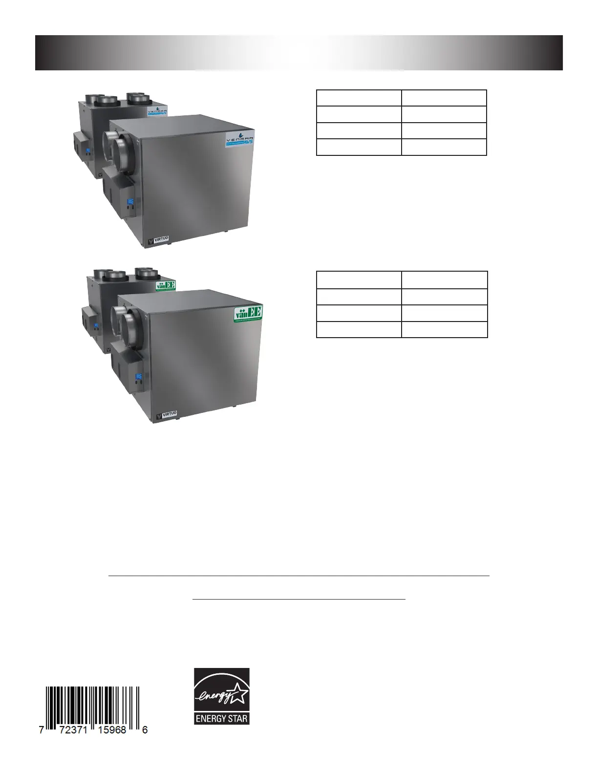
VB0359
VB0360
REGISTER YOUR PRODUCT ONLINE AT:
www.venmar.ca/register-your-product.html or
www.vanee.ca/en/register-your-product.html
For additional information, visit venmar.ca or vanee.ca
A180H75rT*
A180E75RT*
A230H75RT* A230H75RS*
A210E75RT* A210E75RS*
v180H75rT*
V180E75RT*
V230H75RT* V230H75RS*
V210E75RT* V210E75RS*
Venmar Ventilation ULC, 550 Lemire Blvd., Drummondville, Québec, Canada J2C 7W9 venmar.ca / vanee.ca 800-567-3855
*THese producTs eArned THe enerGY
sTAr
®
bY meeTinG sTricT enerGY efficiencY
Guidelines seT bY nATurAl resources cAnAdA
And THe us epA. THeY meeT enerGY sTAr
requiremenTs onlY wHen used in cAnAdA.

2
Please take note that this manual uses the following symbols to emphasize particular information:
Identies an instruction which, if not followed, might cause serious personal injuries including possibility of
death.
CAUTION
Denotes an instruction which, if not followed, may severely damage the unit and/or its components.
NOTE: Indicates supplementary information needed to fully complete an instruction.
LIMITATION
For an installation and use in Canada only. Intended for a building on which Part 9 of division B from the effective version
ot the National Building Code of Canada applies with additional restrictions and exception (see page 25 for more details).
Installation work and electrical wiring must be done by a qualied person in accordance with all applicable codes and
standards, including re-rated construction codes and standards.
⚠WARNING
TO REDUCE THE RISK OF FIRE, ELECTRIC SHOCK, OR INJURY TO PERSON(S) OBSERVE THE FOLLOWING:
1. Use this unit only in the manner intended by the manufacturer.
2. Before servicing or cleaning this unit, disconnect power cord from electrical outlet.
3. This unit is not designed to provide combustion and/or dilution air for fuel-burning appliances.
4. When cutting or drilling into a wall or ceiling, do not damage electrical wiring and other hidden utilities.
5. Do not use this unit with any solid-state speed control device other than those specied in section 3.1.
6. This unit must be grounded. The power supply cord has a 3-prong grounding plug for your personal safety. It must be
plugged into a mating 3-prong grounding receptacle, grounded in accordance with the national electrical code and local
codes and ordinances. Do not remove the ground prong. Do not use an extension cord.
7. Do not install in a cooking area or connect directly to any appliances.
8. Do not use to exhaust hazardous or explosive materials and vapors.
9. When performing installation, servicing or cleaning this unit, it is recommended to wear safety glasses and gloves.
10. When applicable local regulation comprises more restrictive installation and/or certication requirements, the
aforementioned requirements prevail on those of this document and the installer agrees to conform to these at his own
expenses.
CAUTION
1. To avoid prematurely clogged lters, turn the unit OFF during construction or renovation.
2. Please read specication label on product for further information and requirements.
3. Be sure to duct air outside – Do not intake/exhaust air into spaces within walls or ceiling or into attics, crawl spaces, or
garage. Do not attempt to recover the exhaust air from a dryer or a range hood.
4. Do not run any air ducts directly above or within 2 ft (0.61 m) of a furnace or its supply plenum, boiler, or other heat
producing appliance. If a duct has to be connected to the furnace return plenum, it must be connected 10’ (3.1 m) away
from plenum’s connection to the furnace.
5. The ductwork is intended to be installed in compliance with all applicable local and national codes.
6. When leaving the house for a long period of time (more than two weeks), a responsible person should regularly check
if the unit operates adequately.
7. If the ductwork passes through an unconditioned space (e.g.: attic), the unit must operate continuously except when
performing maintenance and/or repair. Also, the ambient temperature of the house should never drop below 18°C
(65°F).
8. At least once a year, the unit mechanical and electronic parts should be inspected by qualied service personnel.
9. Do not use your unit during construction or renovation of your house or when sanding drywall. Certain types of dust
and vapors may damage your system.
10. Make sure at all times that the outside intake and exhaust hoods are free from any snow during the winter season. It
is important to check your unit during a big snow storm, so it doesn’t draw in any snow. If this is the case, please turn
the unit OFF for a few hours.
11. Since the electronic control system of the unit uses a microprocessor, it may not operate correctly because of external
noise or very short power failure. If this happens, unplug the unit and wait approximately 10 seconds. Then, plug the
unit in again.
12. Do not make excessive use of fragrance appliances or chemicals since some may damage the unit components material.
⚠WARNING

3
TABLE OF CONTENT
1. TECHNICAL DATA ...............................................................................................................4
1.1 AIR DISTRIBUTION (NORMAL OPERATION) .............................................................................................4
2. INSTALLATION ....................................................................................................................4
2.1 LOCATING AND MOUNTING THE UNIT .....................................................................................................4
2.2 INSTALLING THE DUCTWORK AND THE REGISTERS .............................................................................6
2.2.1 Fully DucteD SyStem (t-1) (thiS conFiguration allowS recirculation moDe to operate.) ............................6
2.2.2 exhauSt DucteD SyStem (t-2) (thiS conFiguration allowS recirculation moDe to operate.) .......................6
2.2.3 SimpliFieD inStallation (t-4) (thiS conFiguration DoeS not allow recirculation moDe to operate.) ..............7
2.3 CONNECTING THE DRAIN (HRV ONLY) .................................................................................................... 8
2.4 INSTALLING THE EXTERIOR HOODS .......................................................................................................9
2.5 CONNECTING THE DUCTS TO THE UNIT ................................................................................................. 9
2.5.1 DuctS connection .................................................................................................................................10
3. CONNECTIONS .................................................................................................................11
3.1 ELECTRICAL CONNECTION TO OPTIONAL MAIN WALL CONTROL .................................................... 11
3.1.1 electrical connection to DehumiDiStat or automatic optional main wall control ................................ 11
3.1.2 electrical connection to aDvanceD optional main wall control .......................................................... 11
3.2 ELECTRICAL CONNECTION TO OPTIONAL AUXILIARY WALL CONTROL ...........................................12
3.2.1 electrical connection to 20-40-60 optional auxiliary wall control ...................................................12
3.2.2 electrical connection to Dry contact optional auxiliary wall control (e.g. crank timer) .................12
3.3 CONNECTION TO THE CENTRAL FORCED-AIR SYSTEM .....................................................................13
3.3.1 unit operation uSing a Dry contact connection...................................................................................13
3.3.2 unit interconnection with central ForceD-air SyStem (r/c/g/gF) .......................................................13
3.3.3 Synchronization with central ForceD-air SyStem Function ...................................................................13
4. WIRING DIAGRAM ............................................................................................................14
5. NAVIGATION ON LCD SCREEN ....................................................................................... 15
5.1 LCD SCREEN ............................................................................................................................................16
5.2 UNIT FIRST BOOT .....................................................................................................................................16
5.3 SETTINGS MODIFICATION .......................................................................................................................16
5.3.1 proceDure to moDiFy min cFm Setting ....................................................................................................16
5.3.2 proceDure to moDiFy max cFm Setting ...................................................................................................16
5.3.3 proceDure to moDiFy optionS Setting...................................................................................................16
5.3.4 proceDure to moDiFy inDepenDent airFlowS Setting ..............................................................................16
5.4 FACTORY SETTINGS RESET ................................................................................................................... 17
6. USING THIS UNIT ..............................................................................................................17
6.1 YOUR VENTILATION SYSTEM ..................................................................................................................17
6.2 INTEGRATED CONTROL ..........................................................................................................................17
6.3 AHU MODE DISPLAY ................................................................................................................................17
7. SERVICE PARTS ................................................................................................................ 18
8. INSTALLER’S TROUBLESHOOTING ...............................................................................20
8.1 ELECTRONIC PROTECTION TO PREVENT ABNORMAL HIGH STATIC PRESSURE ............................22
9. MAINTENANCE .................................................................................................................23
9.1 QUARTERLY ..............................................................................................................................................23
9.2 ANNUAL (AT FALL) ....................................................................................................................................24
10. USER’S TROUBLESHOOTING .......................................................................................24
11. WARRANTY ......................................................................................................................25
Product Specifications
| Brand: | VänEE |
| Category: | Air conditioning |
| Model: | V180E75RT |
Do you need help?
If you need help with VänEE V180E75RT, ask a question below and other users will answer you
Air conditioning VänEE User Manuals

14 October 2024
14 October 2024
14 October 2024
14 October 2024
13 October 2024
13 October 2024
13 October 2024
13 October 2024
13 October 2024
Air conditioning User Manuals
- Air conditioning Candy
- Air conditioning Electrolux
- Air conditioning Samsung
- Air conditioning LG
- Air conditioning Panasonic
- Air conditioning Delonghi
- Air conditioning Koldfront
- Air conditioning Arcelik
- Air conditioning Danby
- Air conditioning Hisense
- Air conditioning Gree
- Air conditioning TCL
- Air conditioning Hotpoint
- Air conditioning Whirlpool
- Air conditioning Cecotec
- Air conditioning Comfee
- Air conditioning Kogan
- Air conditioning SereneLife
- Air conditioning Create
- Air conditioning Midea
- Air conditioning Sauber
- Air conditioning Haier
- Air conditioning Olimpia Splendid
- Air conditioning Westinghouse
- Air conditioning Sencor
- Air conditioning Electroline
- Air conditioning Fujitsu
- Air conditioning Orava
- Air conditioning Mistral
- Air conditioning Khind
- Air conditioning Amana
- Air conditioning Dimplex
- Air conditioning Whynter
- Air conditioning GE
- Air conditioning Hitachi
- Air conditioning Hyundai
- Air conditioning Daikin
- Air conditioning Be Cool
- Air conditioning Avidsen
- Air conditioning Mitsubishi
- Air conditioning Friedrich
- Air conditioning Tristar
- Air conditioning Dometic
- Air conditioning Eldom
- Air conditioning Elba
- Air conditioning Philco
- Air conditioning Black And Decker
- Air conditioning Wilfa
- Air conditioning Heinner
- Air conditioning SEEGER
- Air conditioning IFB
- Air conditioning Duracraft
- Air conditioning Home Electric
- Air conditioning Milectric
- Air conditioning LERAN
- Air conditioning Perfect Aire
- Air conditioning Argoclima
- Air conditioning ARCTIC WIND
- Air conditioning Trisa
- Air conditioning Daizuki
- Air conditioning Mayer
- Air conditioning Be Quiet!
- Air conditioning BOSFOR
- Air conditioning KDK
- Air conditioning Aconatic
- Air conditioning AireMax
- Air conditioning Profile
- Air conditioning Keystone
- Air conditioning Honeywell
- Air conditioning Ravanson
- Air conditioning ActronAir
- Air conditioning Woods
- Air conditioning Aspes
- Air conditioning Fuave
- Air conditioning Yamazen
- Air conditioning Cool-Space
- Air conditioning GoldAir
- Air conditioning KuulAire
- Air conditioning SHE
- Air conditioning BLUEPALM
Latest Air conditioning User Manuals

27 October 2024
27 October 2024
27 October 2024
27 October 2024
27 October 2024
27 October 2024

27 October 2024
27 October 2024
26 October 2024
26 October 2024