Vimar 03823 Manual
Vimar
Alarm system
03823
Read below 📖 the manual in Italian for Vimar 03823 (4 pages) in the Alarm system category. This guide has been helpful for 31 people and has been rated 4.5 stars on average by 2 users
Page 1/4
Viale Vicenza, 14
36063 Marostica VI - Italy
www.vimar.com
49401696A0 02 2301
03823
BY-ALARM PLUS
Interfaccia By-alarm Plus isolata per rigenerazione del segnale BUS.
Il dispositivo, connesso al BUS, consente di aumentare l'estensione e l'integrità funzionale del
BUS nella trasmissione dei dati. Svolge quindi funzioni di isolamento BUS e rigenerazione del
segnale sul BUS; è provvisto di alimentazione e convertitore DC/DC isolati ed è fornito in conte-
nitore plastico chiuso con protezione antiapertura ed antistrappo.
COLLEGAMENTI E FUNZIONALITÀ
Il dispositivo è provvisto di 4 morsetti ai quali collegare il BUS in ingresso e 4 morsetti cui collegare
il BUS in uscita. Le sue funzionalità sono:
• isolamento galvanico, fino a 2750 V, della linea dati del BUS (“D” e “S”) tra ingresso ed uscita;
• isolamento galvanico dell’alimentazione sul BUS (“+” e “-”), tramite il taglio di ponticelli di iso-
lamento disponibili sulla scheda;
• rigenerazione dei segnali di comunicazione, limitando le perdite dovute ad una lunghezza
eccessiva del cavo BUS;
• rilevamento di anomalie di funzionamento verso il ramo di uscita e conseguente isolamento
del ramo stesso.
ISOLAMENTO E MODALITÀ DI INTERVENTO
Il dispositivo permette di creare due gruppi di periferiche tramite l’isolamento galvanico dell’a-
limentazione, della massa e dei canali dati D e S di ciascun gruppo. Si può così separare
un gruppo di periferiche collegato e alimentato direttamente dalla centrale (“gruppo A”)
dal gruppo invece collegato alla centrale tramite isolatore e non alimentato dalla centrale
(“gruppo B”).
La funzione di protezione avviene isolando il gruppo B nel caso in cui il dispositivo rilevi in tale
gruppo i seguenti malfunzionamenti:
- corto tra i terminali “+” e “-”
- corto tra i terminali “D” e “+” oppure “D” e “-”
- corto tra i terminali “S” e “+” oppure “S” e “-”
- corto tra i terminali “D” e “S”
- assorbimento di corrente superiore a 1 A tra i terminali “+” e “-”
Quando viene rilevato il malfunzionamento il dispositivo provvederà ad isolare il gruppo B, pro-
teggendo il gruppo A. L'isolamento rimarrà attivo per 10 s o fino al successivo reset di centrale.
N.B. Il dispositivo permette l'isolamento galvanico sia dei segnali “D” e “S” che dell’alimentazione.
Il convertitore DC/DC alimenta i dispositivi del gruppo B e quindi non è necessaio un alimentatore
esterno; la tensione di alimentazione di uscita fornita dal convertitore è 13.8 V.
INSTALLAZIONE
1. Scegliere la posizione idonea all’installazione del dispositivo.
2. Aprire il dispositivo.
2. Fissare il dispositivo all'interno della scatola.
3. Far passare i cavi attraverso i fori passacavi e cablare il dispositivo.
4. Montare il dispositivo antisabotaggio da utilizzare per la protezione del dispositivo.
5. Richiudere la scatola.
N.B. Si sconsiglia di posizionare un isolatore subito dopo la centrale. Ogni isolatore andrebbe
posizionato nei punti dove la qualità del BUS si abbassa drasticamente.
Per una corretta installazione del dispositivo (e quindi del BUS) è necessario dimensionare il ramo
del BUS in cui si trova l’isolatore in base al numero di periferiche collegate a tale ramo e al loro
assorbimento di corrente complessivo; tale valore è poi da confrontare con il dato “Assorbimento
massimo da centrale”.
Un'altra caratteristica importante è la lunghezza della linea che si trova a valle dell’isolatore fino
all’isolatore successivo o alla fine della linea. Nella tabella che segue sono indicati i valori di tale
lunghezza in relazione alla velocità del BUS.
Velocità del BUS Lunghezza del cavo a valle dell’isolatore (L)
Numero massimo
di isolatori in cascata
125 kbps 350 m 6
250 kbps 200 m 2
Le lunghezze ( ) vengono identificate con:L
• lunghezza dei cavi tra un isolatore e le periferiche successive o tra due isolatori successivi nel
caso di una linea singola.
• la somma delle lunghezze di tutte le linee che partono da un isolatore e che arrivano ad isolatori
successivi o terminano con delle periferiche nel caso di linee ramificate.
Antisabotaggio
Il dispositivo è provvisto di protezione antiapertura e antistrappo della scatola mediante un
microswitch che invia il segnale per alla centrale tramite il terminale “TAMPER”. Questo terminale
è normalmente chiuso; rimuovendo il ponticello dai connettori di abilitazione antisabotaggio si
disabilita la funzione di protezione.
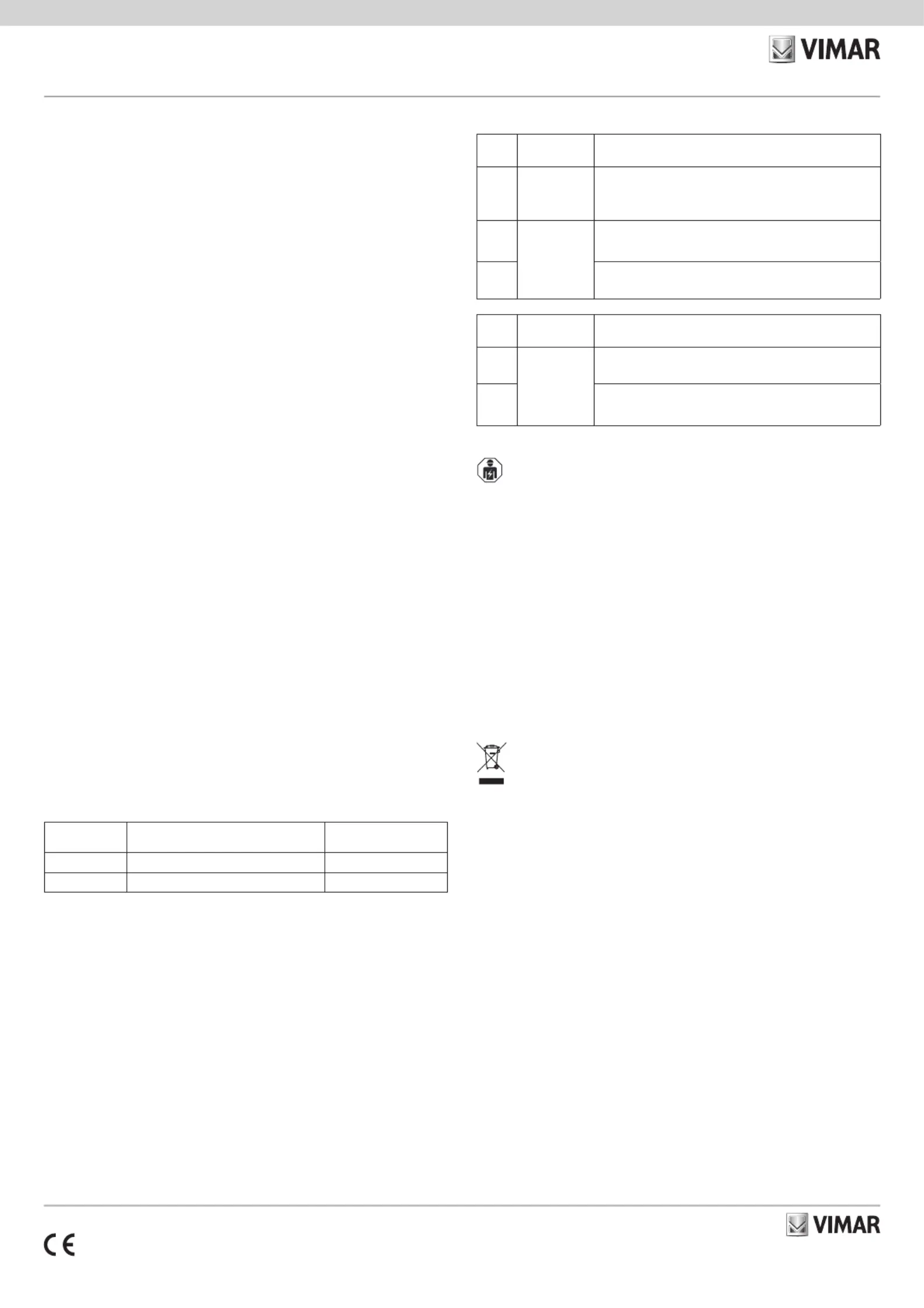
SEGNALAZIONI DEI LED
LED
G*
Colore Significato
DL1 Rosso
Spento: isolamento non attivo (funzionamento normale)
Acceso fisso: isolamento attivo (il BUS-A e il BUS-B sono isolati)
Lampeggiante: isolamento attivo a seguito di corrente > 1A
DL2
Giallo
Spento o : nessuna attività sul BUS-AAcceso fisso
Lampeggiante: attività sul BUS-A (funzionamento normale)
DL3
Spento o : nessuna attività sul BUS-BAcceso fisso
Lampeggiante: attività sul BUS-B (funzionamento normale)
LED
N*
Colore Significato
DL1
Verde
Spento: alimentazione non presente sul BUS-A
Acceso: alimentazione presente sul BUS-A
DL2
Spento: alimentazione non presente sul BUS-B
Acceso: alimentazione presente sul BUS-B
* Per la posizione di G ed N si veda la figura "VISTA FRONTALE (dopo apertura del coperchio)".
REGOLE DI INSTALLAZIONE
L’installazione deve essere effettuata da personale qualificato con l’osservanza delle disposizioni
regolanti l’installazione del materiale elettrico in vigore nel paese dove i prodotti sono installati.
CARATTERISTICHE
• Tensione di ingresso: da 9,5 V a 15 V
• Corrente assorbita: 130 mA
• Corrente max disponibile sul morsetto "+" del lato B: 1 A
• Convertitore DC/DC con tensione di uscita 13,8 V
• Temperatura di funzionamento: da -10 a +40 °C
• Grado di sicurezza: 3
• Classe ambientale: II
• Dimensioni (L x A x P): 172 x 809 x 27 mm
CONFORMITA' NORMATIVA.
Direttiva EMC. Direttiva RoHS.
Norme EN 50131-3, EN 50130-4, EN 50130-5, EN 55032, EN IEC 63000.
Regolamento REACh (UE) n. 1907/2006 – art.33. Il prodotto potrebbe contenere tracce di
piombo.
RAEE - Informazione agli utilizzatori
Il simbolo del cassonetto barrato riportato sull’apparecchiatura o sulla sua confezione indica che il prodotto alla fine della pro-
pria vita utile deve essere raccolto separatamente dagli altri rifiuti. L’utente dovrà, pertanto, conferire l’apparecchiatura giunta
a fine vita agli idonei centri comunali di raccolta differenziata dei rifiuti elettrotecnici ed elettronici. In alternativa alla gestione
autonoma, è possibile consegnare gratuitamente l’apparecchiatura che si desidera smaltire al distributore, al momento dell’ac-
quisto di una nuova apparecchiatura di tipo equivalente. Presso i distributori di prodotti elettronici con superficie di vendita di
almeno 400 m
2
è inoltre possibile consegnare gratuitamente, senza obbligo di acquisto, i prodotti elettronici da smaltire con
dimensioni inferiori a 25 cm. L’adeguata raccolta differenziata per l’avvio successivo dell’apparecchiatura dismessa al riciclag-
gio, al trattamento e allo smaltimento ambientalmente compatibile contribuisce ad evitare possibili effetti negativi sull’ambiente
e sulla salute e favorisce il reimpiego e/o riciclo dei materiali di cui è composta l’apparecchiatura.
Viale Vicenza, 14
36063 Marostica VI - Italy
www.vimar.com
49401696A0 02 2301
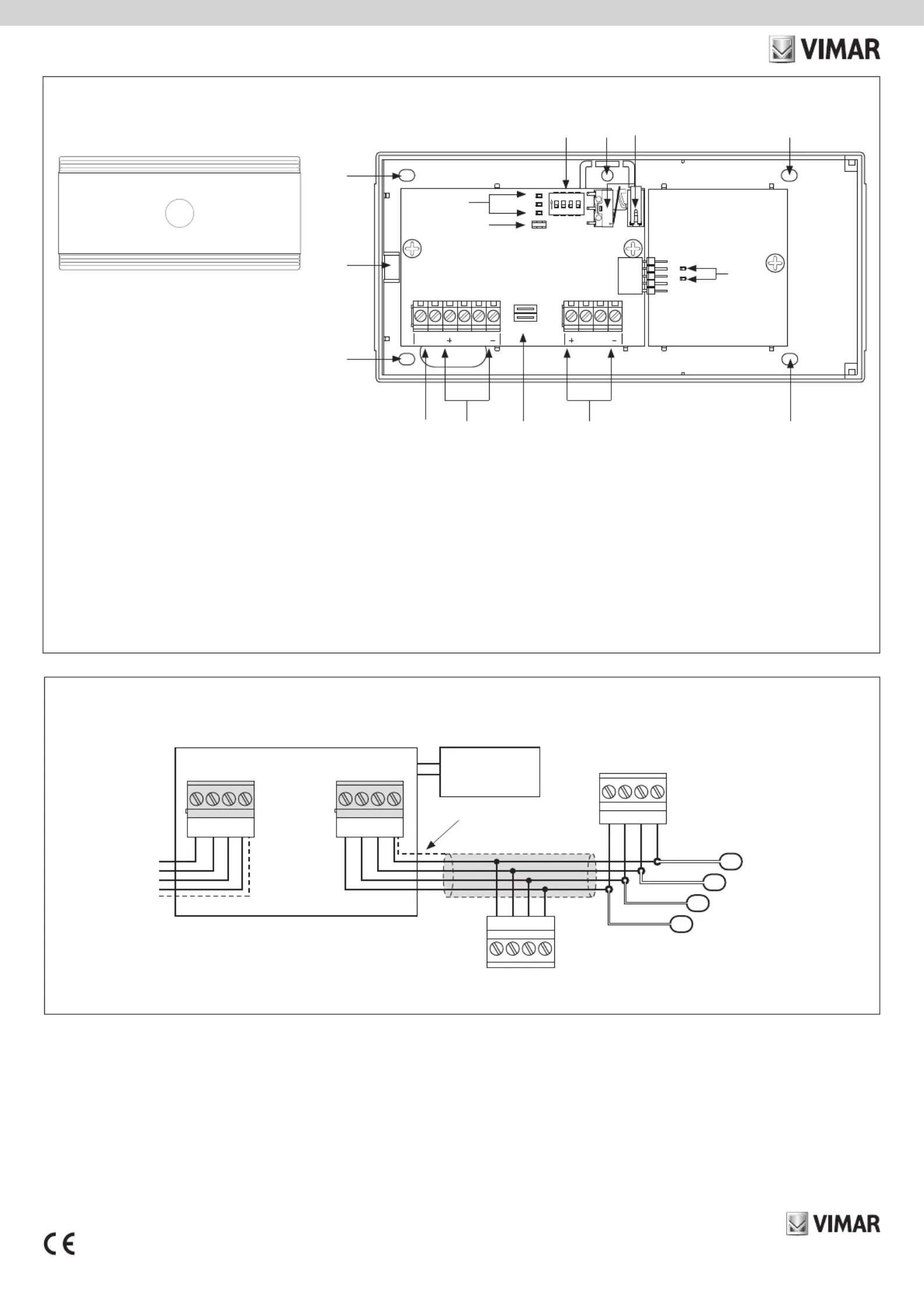
VISTA FRONTALE (dopo apertura del coperchio)
A: Morsetti +, Db, Sb, - per il collegamento al BUS B (in corrispondenza di +, D, S, - rispettivamente)
B: Ponticelli non utilizzati
C: Morsetti +, Da, Sa, - per il collegamento al BUS A verso la centrale (in corrispondenza di +, D, S, - rispettivamente)
D: Morsetti per segnalazione antisabotaggio alla centrale
E: Foro di fissaggio
F: Foro per vite di chiusura coperchio
G: Led DL1, DL2, DL3 (isolamento, comunicazione BUS A e comunicazione BUS B)
H: Connettori per abilitazione antisabotaggio (si veda paragrafo Antisabotaggio)
I: Dip-switch non utilizzati
L: Foro antistrappo
M: Switch antisabotaggio
N: Led DL1, DL2 (alimentazione BUS A e alimentazione BUS B)
COLLEGAMENTI
A
B
E
C
J1
PWR-OUT
PWR-IN
DL1
DL2
SW1
1
ON
SDA04
C&K
234
SW2SW3
DL3
DL2
DL1
TAMPER-EN
J8
1 2
DaTAMPER Sa
3 4 5 6 7 8 9 10
JP2JP1
J7
tyco
Db
ISOLATE
BUS-B
BUS-A
Sb
D
F
E
G
H
I
E
N
E
L M
D+ –S
D+ –S
D+ –S
S
–
D
+
D+ –S
Dispositivi BUS
BUS
Dispositivi BUS
GRUPPO A
GRUPPO B
03823
Calza
A B
Alimentatore
Viale Vicenza, 14
36063 Marostica VI - Italy
www.vimar.com
49401696A0 02 2301
03823
BY-ALARM PLUS
By-alarm interface isolated for BUS signal regeneration.
When connected to the BUS, this device increases the BUS data transmission range and integ-
rity. It serves to isolate and regenerate the BUS signal. It has an isolated power supply and DC/
DC converter, and is supplied in a plastic enclosure with anti-tamper and anti-removal protection.
CONNECTIONS AND FUNCTIONS
The device has 4 terminals for connecting the BUS input and 4 terminals for connecting the BUS
output. It performs the following functions:
• galvanic isolation between the BUS data input and output line (“D” and “S”) up to 2750 V;
• galvanic isolation of the BUS power supply (“+” and “-”) by cutting the isolation jumpers avail-
able on the board;
• communication signal regeneration, limiting losses due to excessive BUS cable length;
• detecting functional faults on the output branch and consequently isolating the branch.
ISOLATION AND TRIP MODE
The device can be used to create two groups of peripherals by galvanically isolating the power
supply, earth and D and S data channels of each group. A group of peripherals connected to
and powered directly by the control unit (“group A”) can be separated from a group con-
nected to the control unit via the isolator and not powered by the control unit (“group B”).
Protection is provided by isolating group B if the device detects one of the following faults in
that group:
- short between the “+” and “-” terminals
- short between the “D” and “+” or between the “D” and “-” terminals
- short between the “S” and “+” or between the “S” and “-” terminals
- short between the “D” and “S” terminals
- absorption current greater than 1 A between the “+” and “-” terminals
When a fault is detected, the device will isolate group B to protect group A. Isolation will remain
active for 10 s or until the control unit is reset.
N.B. The device isolates both the “D” and “S” signals and the power supply. The DC/DC con-
verter powers the group B devices, so there is no need for an external power supply unit; the
converter supplies an output voltage of 13.8 V.
INSTALLATION
1. Choose a suitable location to install the device.
2. Open the device.
2. Fasten the device inside the box.
3. Route the cables through the cable outlet holes and wire the device.
4. Fit the anti-tamper device used to protect the device.
5. Close the box.
N.B. We recommend fitting an isolator immediately after the control unit. Fit each isolator at
a point where the BUS signal quality is significantly reduced.
To install the device (and therefore the BUS) correctly, dimension the BUS branch with the isolator
according to the number of peripherals connected thereto and their total current absorption; then
compare this value with the “Maximum control unit absorption” value.
Another important characteristic is the line length downstream of the isolator up to the next isola-
tor or to the end of the line. The table below shows the cable length in relation to the BUS speed.
BUS speed Cable length downstream of the isolator (L)
Maximum number
of cascaded isolators
125 kbps 350 m 6
250 kbps 200 m 2
The lengths ( ) are identified with:L
• cable length between one isolator and the subsequent peripherals or between successive
isolators for a single line.
• the sum of the lengths of all lines between an isolator and the subsequent isolators, or going
to peripherals for branched lines.
Anti-tamper
The device box has anti-tamper and anti-removal protection based on a microswitch that sends
a signal to the control unit via the “TAMPER” terminal. This terminal is normally closed; removing
the jumper from the anti-tamper enable connectors disables the protection function.
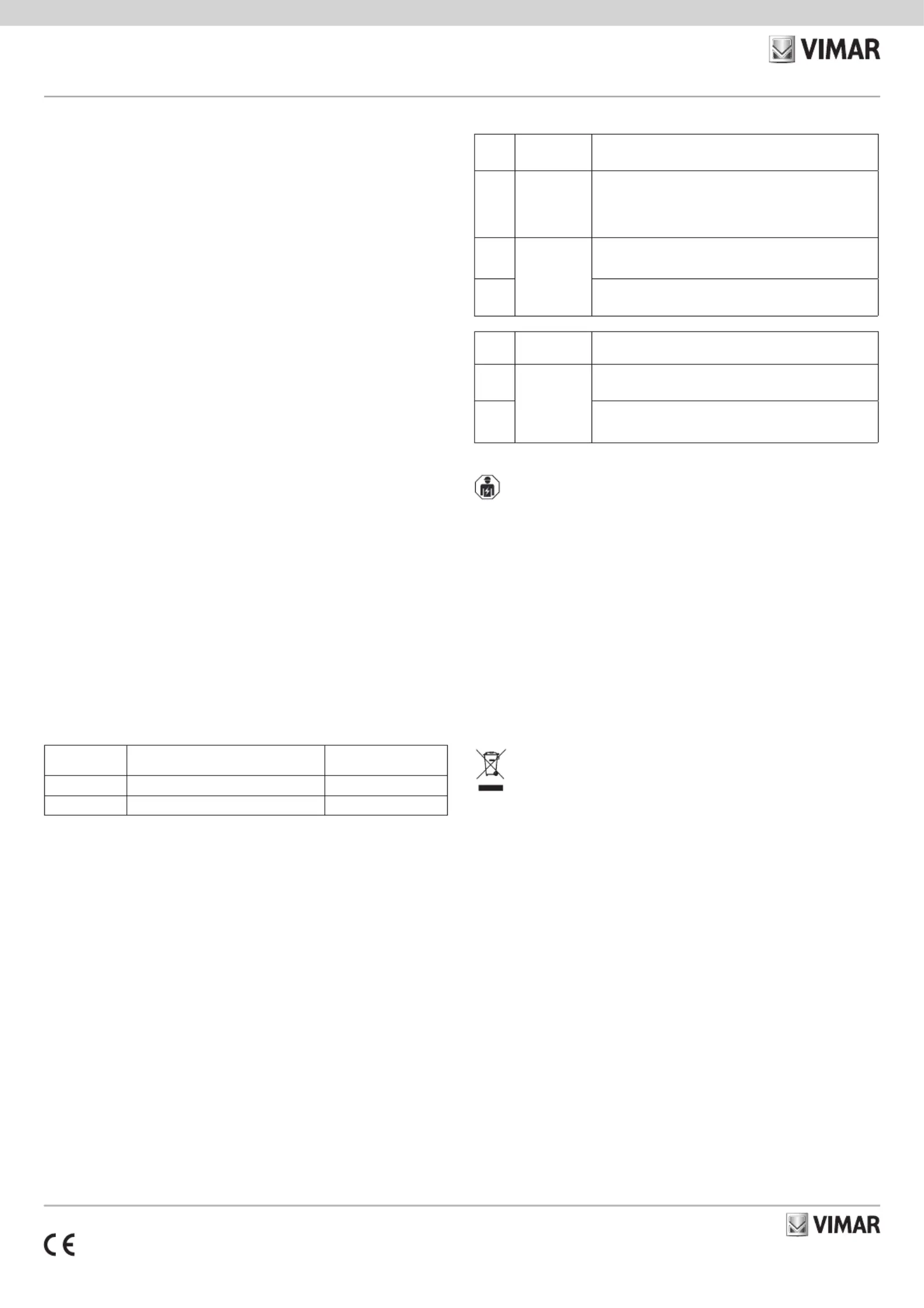
LED INDICATIONS
LED
G*
Colour Meaning
DL1 Red
OFF: insulation not active (standard operation)
Permanently ON: insulation active (BUS-A and BUS-B are
insulated)
Flashing: insulation active following current > 1A
DL2
Yellow
OFF or Permanently ON: no activity on BUS-A
Flashing: activity on BUS-A (standard operation)
DL3
OFF or Permanently ON: no activity on BUS-B
Flashing: activity on BUS-B (standard operation)
LED
N*
Colour Meaning
DL1
Green
OFF: power supply not present on BUS-A
ON: power supply present on BUS-A
DL2
OFF: power supply not present on BUS-B
ON: power supply present on BUS-B
* For the position of G and N see figure "FRONT VIEW (after opening the cover)".
INSTALLATION RULES
Installation must be carried out by qualified persons in compliance with the current regulations
regarding the installation of electrical equipment in the country where the products are installed.
CHARACTERISTICS
• Input voltage: 9.5 V to 15 V
• Absorbed current: 130 mA
• Max current available from the "+" terminal on side B: 1 A
• DC/DC converter with output voltage of 13.8 V
• Operating temperature: -10 to +40 °C
• Safety class: 3
• Environment class: II
• Dimensions (W x H x D): 172 x 809 x 27 mm
REGULATORY COMPLIANCE.
EMC directive. RoHS directive.
Standards EN 50131-3, EN 50130-4, EN 50130-5, EN 55032, EN IEC 63000.
REACH (EU) Regulation no. 1907/2006 – Art.33. The product may contain traces of lead.
WEEE - User information
The crossed bin symbol on the appliance or on its packaging indicates that the product at the end of its life must be collect-
ed separately from other waste. The user must therefore hand the equipment at the end of its life cycle over to the appro-
priate municipal centres for the differentiated collection of electrical and electronic waste. As an alternative to independent
management, you can deliver the equipment you want to dispose of free of charge to the distributor when purchasing a
new appliance of an equivalent type. You can also deliver electronic products to be disposed of that are smaller than 25
cm for free, with no obligation to purchase, to electronics distributors with a sales area of at least 400 m
2
. Proper sorted
waste collection for subsequent recycling, processing and environmentally conscious disposal of the old equipment helps
to prevent any possible negative impact on the environment and human health while promoting the practice of reusing and/
or recycling materials used in manufacture.
Product Specifications
| Brand: | Vimar |
| Category: | Alarm system |
| Model: | 03823 |
Do you need help?
If you need help with Vimar 03823, ask a question below and other users will answer you
Alarm system Vimar User Manuals

14 October 2024
14 October 2024
14 October 2024
14 October 2024
14 October 2024
Alarm system User Manuals
- Alarm system IKEA
- Alarm system Schwaiger
- Alarm system Bearware
- Alarm system Qolsys
- Alarm system ORNO
- Alarm system Hikvision
- Alarm system Dometic
- Alarm system EVOLVEO
Latest Alarm system User Manuals
26 October 2024
26 October 2024
26 October 2024
24 October 2024
22 October 2024
15 October 2024
15 October 2024
13 October 2024

13 October 2024
13 October 2024