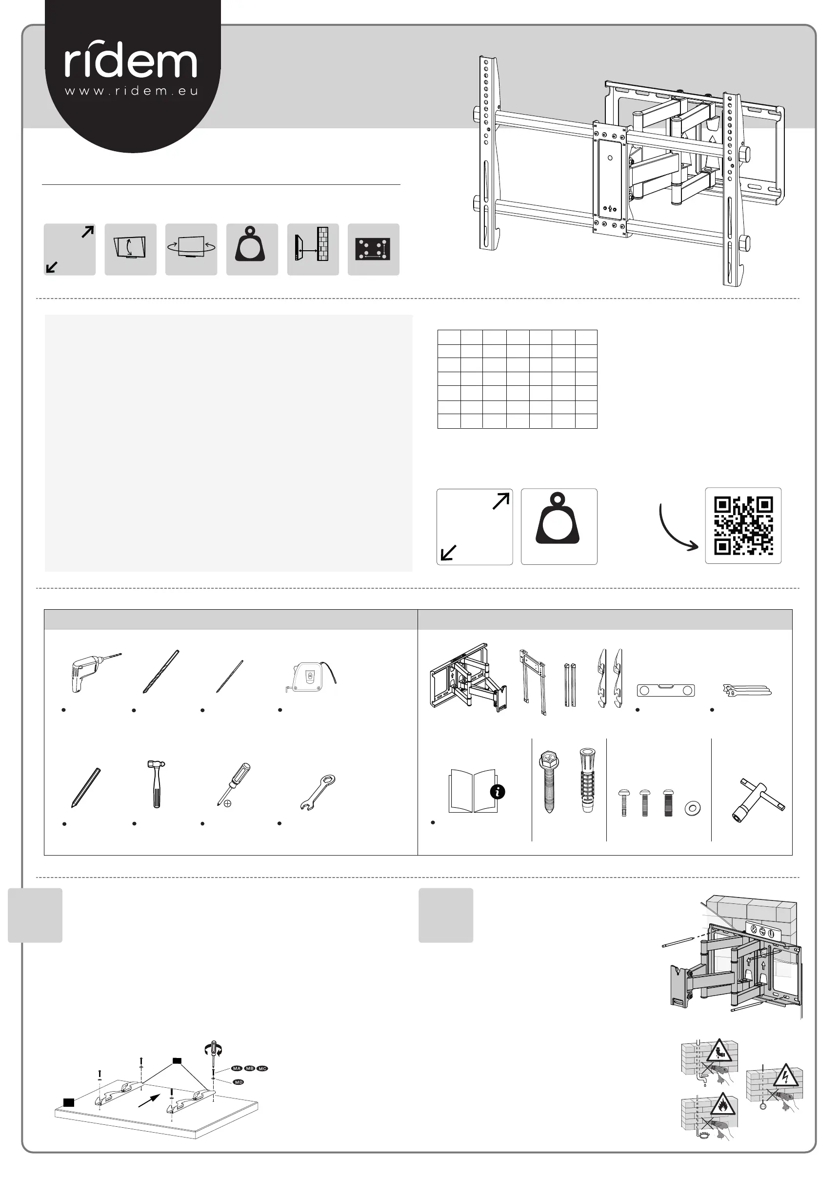
Ridem RDM S4 Manual
Ridem
wall support
RDM S4
Read below 📖 the manual in Italian for Ridem RDM S4 (2 pages) in the wall support category. This guide has been helpful for 24 people and has been rated 4.5 stars on average by 2 users
Page 1/2
Manuale di Istruzioni - Instruction Manual
Instructions de montage - Montage anleitung - Guia de montaje - Instrucoes de montagem
SUPPORTO TV
wall mount
IT
Prima di procedere all’installazione, vericate la compatibilità della staa con la vostra TV. La tabella VESA mostra la distanza
dei fori che trovate sul retro della TV. Valutate inoltre l’idoneità della parete dove andrete ad applicare la staa. Nel dubbio,
sia per la scelta della staa che per il montaggio, rivolgetevi ad un installatore professionista.
EN
Before proceeding with the installation, check the compatibility of the bracket with your TV. The VESA table shows the
distance of the holes on the back of the TV. Also evaluate the suitability of the wall where you will apply the bracket. If in
doubt, both for the TV mount choice and for its assembly, contact a professional installer.
FR
Avant de procéder à l'installation, vériez la compatibilité du support avec votre téléviseur. Le tableau VESA indique la
distance des trous qui se trouve à l'arrière du téléviseur. Évaluez également la conformité du mur où vous appliquerez le
support. En cas de doute sur le choix du support ou pour le montage, contactez un installateur professionnel.
DE
Bevor Sie mit der Installation fortfahren, überprüfen Sie die Kompatibilität der Halterung mit Ihrem Fernseher. Das
VESA-Diagramm zeigt den Abstand der Löcher auf der Rückseite des Fernsehers. Bewerten Sie auch die Eignung der Wand, an
der Sie die Halterung anbringen werden. Wenden Sie sich im Zweifel sowohl bei der Auswahl der Halterung als auch bei der
Montage an einen professionellen Installateur.
ES
Antes de continuar con la instalación, verique la compatibilidad del soporte con su televisor. El gráco VESA muestra la
distancia de los agujeros que se encuentran en la parte posterior del televisor. Evalúe también la idoneidad de la pared
donde aplicará el soporte. En caso de duda, tanto para la elección del soporte como para el montaje, contacte con un
instalador profesional.
PT
Antes de prosseguir com a instalação, verique a compatibilidade do suporte com a TV. A tabela VESA mostra a distância
dos orifícios na parte traseira da TV. Avalie também a adequação da parede onde irá aplicar o suporte. Em caso de dúvida,
tanto para a escolha do suporte da TV quanto para a montagem, entre em contato com um instalador prossional.
Scan
me
IT - Per maggiori info sulla linea RIDEM e per consultare le
condizioni di garanzia, visitate il sito: www.ridem.eu
EN - Per maggiori info sulla linea RIDEM e per consultare
le condizioni di garanzia, visitate il sito: www.ridem.eu
FR - Pour plus d’infos sur la ligne RIDEM et pour consulter
les conditions de garantie, visitez le site: www.ridem.eu
DE - Für weitere Informationen über die RIDEM-Linie und
um die Garantiebedingungen einzusehen, besuchen Sie
die Website: www.ridem.eu
ES - Para obtener más información sobre la línea RIDEM y
consultar las condiciones de garantía, visite el sitio web:
www.ridem.eu
PT - Para mais informações sobre a linha RIDEM e para
consultar as condições de garantia visite o site:
www.ridem.eu
Utensili necessari/ Reccomended tools
Contenuto della confezione/ Inside the box
COMPATIBILITÀ/ COMPATIBILITY
*VESA is a registered Trademark of the Video Electronics Standards
Association
VESA 75 100 200 300 400 600
75
100
200
300
400
600
*
1 2
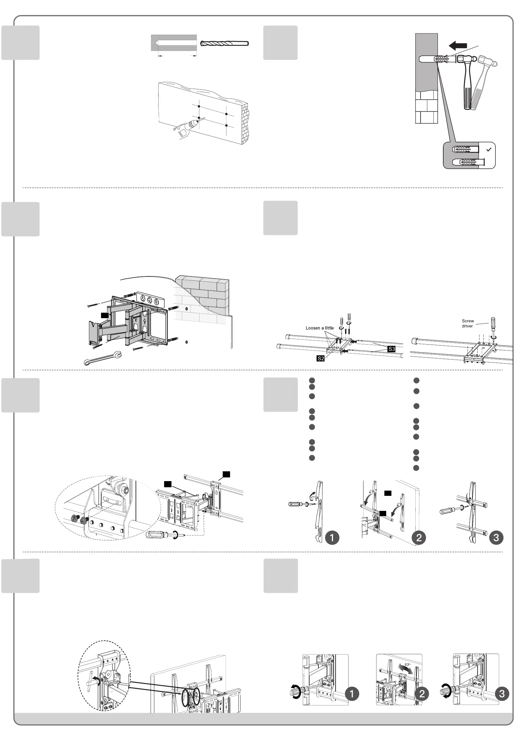
Appoggiando la staffa alla parete, marcate i punti dove
effettuare i fori. Prima di forare accertatevi che non vi siano
cavi o tubi nella parete.
Position the bracket on the wall and mark the points where
to drill the holes. Before drilling make sure that there are no
cables or pipes inside the wall.
En posant le support sur le mur, marquez les endroits où les
trous doivent être faits.Avant de percer, assurez-vous qu’il
n’y a pas de câbles ou de tuyaux dans le mur.
Lehnen Sie die Halterung an die Wand und markieren Sie die
Punkte, an denen die Löcher angebracht werden sollen.
Bevor Sie die Löcher bohren, stellen Sie sicher dass keine
Kabel oder Rohre in der Wand sind.
Apoyando el soporte contra la pared, marque los puntos
donde hacer los agujeros.Antes de perforar, asegúrese de
que no haya cables o tuberías en la pared.
Posicione o suporte na parede e marque os pontos onde
fazer os furos. Antes de perfurar, certifique-se de que não há
cabos ou tubos dentro da parede.
IT
EN
FR
DE
ES
PT
Martello
Hammer
Trapano
Drill
Metro
Measuring tape
Matita
Pencil
Ø10 mm
3/8”
Ø5,5 mm
7/32”
Livella a bolla
Bubble level
Manuale di istruzioni
Instruction manual
x4x4x4
B
x4
A
x4 x4
C
P1 S2
S3
S4
MA
MB
MC
MD
Fascette fissacavo
Cable ties
Cacciavite
Screwdriver
Appoggiate al retro della TV le due staffe verticali (S4) e
fissatele ai fori della TV utilizzando le viti adatte
(MA-MB-MC). Riferitevi alla figura per posizionare
correttamente le viti nelle rondelle (MD). Chiameremo la
TV con le due staffe P3.
Place the two vertical brackets (S4) on the TV's back and
fix them to the TV holes, using the suitable screws
(MA-MB-MC). Refer to the picture to insert correctly the
screws into the washers (MD). The TV with the two
brackets will be named P3.
Placez les deux supports verticaux (S4) à l'arrière du
téléviseur et fixez-les aux trous du téléviseur à l'aide des
vis appropriées (MA-MB-MC). Se référer à la figure pour
positionner correctement les vis dans les rondelles (MD).
Nous appellerons le téléviseur avec les deux supports P3.
IT
EN
FR
Platzieren Sie die beiden vertikalen Halterungen (S4) auf der
Rückseite des Fernsehgeräts und befestigen Sie sie mit den
entsprechenden Schrauben (MA-MB-MC) an den Löchern des
Fernsehgeräts. Beziehen Sie sich auf die Abbildung, um die
Schrauben richtig in den Unterlegscheiben (MD) zu positionieren.
Wir nennen den Fernseher mit den beiden Klammern P3.
Coloque los dos soportes verticales (S4) en la parte
posterior del televisor y fíjelos a los agujeros del televisor
con los tornillos apropiados (MA-MB-MC). Consulte la
figura para colocar correctamente los tornillos en las
arandelas (MD). Llamaremos al televisor con los dos
soportes P3.
Coloque os dois suportes verticais (S4) na parte traseira
da TV e fixe-os nos orifícios, usando os parafusos
adequados (MA-MB-MC). Consulte a figura para inserir
corretamente os parafusos nas anilhas (MD). A TV com os
dois suportes será identificada por P3.
DE
ES
PT
50 Kg-110 lbs
MAX
6,8/39,5 cm
100/600/200
VESA
TILT -3° +12°
32” to
70”
RDM S4
50 Kg-110 lbs
MAX
32” to
70”
✔
✔
TURN 90°
✔
✔
✔
✔
✔
✔
✔
✔
✔
✔
✔
✔
✔
✔
✔ ✔ ✔
3DJHRI
%
%%
%
5
:
::
:
:
::
:
:
::
:
(
((
(
5
:
::
:
:
::
:
:
::
:
(
((
(
4A
4B
The anchor must be
sunk up to 3/8" / 10 mm
into the plaster coating
10mm
3/8"
x Min 2
Min 4
Max 9
X
2
3/4
" / 70mm
2
3/4
" / 70mm
1/4" / 6mm
3/8" / 10mm
$
$$
$
2
3/4
" / 70mm
5/32" / 4mm
P3
S4
Chiave inglese - 13 mm
Wrench -
1/2”
La linea RIDEM è prodotta e distribuita da:/ RIDEM line is produced and distributed by: KARMA ITALIANA srl - Via Gozzano 38/bis - 21052 Busto Arsizio - www.karmaitaliana.it - Made in China 22.1
5
3
4
6
7 8
9 10
IT
EN
FR
DE
ES
PT
Fissate la staffa (P1) alla parete usando le viti incluse.
Serratele prima tramite cacciavite, quindi con una
chiave inglese.
Fix the bracket (P1) to the wall using the included
screws. Fasten them first with a screwdriver and then
with a wrench.
Fixez le support (P1) au mur à l’aide des vis incluses.
Serrez-les d'abord avec un tournevis, puis avec une clé
à molette.
IT
EN
FR
DE
ES
PT
La staffa è posizionabile unicamente su pareti in
muratura (no legno). Utilizzate la punta da 10mm.
The bracket can only be positioned on masonry walls
(not wood). Use the 10mm bit.
Le support ne peut être positionné que sur des murs en
maçonnerie (pas en bois). Utilisez la mèche de 10 mm.
Die Halterung kann nur bei gemauerten Wänden (nicht
Holz) platziert werden. Verwenden Sie das 10-mm-Bit.
El soporte solo se puede seleccionar en paredes de
mampostería (no de madera). Utilice la broca de 10 mm.
O suporte só pode ser posicionado em paredes de
alvenaria (não de madeira). Use a broca de 10 mm.
IT
EN
FR
DE
ES
PT
Befestigen Sie die Halterung (P1) mit den
mitgelieferten Schrauben an der Wand. Ziehen Sie sie
zuerst mit einem Schraubendreher und dann mit einem
Schraubenschlüssel fest.
Fije el soporte a la pared (P1) con los tornillos incluidos.
Apriételos primero con un destornillador y luego con
una llave.
Fixe o suporte (P1) na parede usando os parafusos
incluídos. Prenda-os primeiro com uma chave de
fenda, depois com uma chave inglesa.
La staffa S2 è fornita premontata, ma occorre
aggiungere le altre due aste S3. Per fare ciò, rimuovete
le 4 viti da S2, inserite i prolungamenti (S3) e serrate le
4 viti che avete tolto, otterrete così il secondo
componente (P2).
The S2 bracket is pre-assembled, but the other two S3
rods must be added. To do this, remove the 4 screws
from S2, insert the extensions (S3) and tighten the 4
screws you removed, you will get the second
component (P2).
Le support S2 est fourni pré-assemblé, mais les deux
autres tiges S3 doivent être ajoutées. Pour ce faire,
retirez les 4 vis de S2, insérez les rallonges (S3) et
serrez les 4 vis que vous avez retirées: vous obtiendrez
le deuxième composant (P2).
IT
EN
FR
Die S2-Halterung wird vormontiert geliefert, aber
die beiden anderen S3-Stangen müssen
hinzugefügt werden. Entfernen Sie dazu die 4
Schrauben von S2, setzen Sie die Verlängerungen
(S3) ein und ziehen Sie die 4 gelösten Schrauben
fest: Sie erhalten die zweite Komponente (P2).
El soporte S2 se ofrece premontado, pero hay que
añadir las otras dos varillas S3. Para ello, quita los 4
tornillos de S2, inserta las extensiones (S3) y aprieta
los 4 tornillos que quitaste, obtendrás el segundo
componente (P2).
O suporte S2 é pré-montado, mas as outras duas
hastes S3 devem ser adicionadas. Para fazer isso,
retire os 4 parafusos de S2, insira as extensões (S3)
e aperte os 4 parafusos que removeu, e assim
obterá o segundo componente (P2).
DE
ES
PT
Rimuovete le viti di sicurezza e sollevate i ganci
Agganciate la TV (P3) alla staffa (P2) posizionan-
dola centralmente.
Chiudete i ganci e riavvitate le due viti di
sicurezza
Remove the safety screws and lift the hooks.
Hook the TV (P3) to the bracket (P2) positioning
it centrally.
Close the hooks and tighten the two safety
screws.
Retirez les vis de sécurité et soulevez les crochets.
Accrochez le téléviseur (P3) au support (P2) en le
positionnant au centre.
Fermez les crochets et serrez les deux vis de
sécurité
IT
EN
FR
Entfernen Sie die Sicherheitsschrauben und
heben Sie die Haken an.
Haken Sie das Fernsehgerät (P3) an der
Halterung (P2) ein und positionieren Sie es
mittig.
Schließen Sie die Haken und ziehen Sie die
beiden Sicherheitsschrauben fest.
Retire los tornillos de seguridad y levante los ganchos.
Enganche el televisor (P3) al soporte (P2)
colocándolo en el centro.
Cierre los ganchos y apriete los dos tornillos de
seguridad.
Retire os parafusos de segurança e levante os ganchos
Encaixe a TV (P3) no suporte (P2)
posicionando-a centralmente.
Feche os ganchos e aperte os dois parafusos de
segurança.
DE
ES
PT
Se il televisore risultasse storto, potrete svitare le due
viti indicate in figura 1, regolare l’inclinazione
orizzontale con l’aiuto di una bolla (fig.2) e quindi
serrare le viti per fissare la posizione (fig.3).
If the TV is not aligned unscrew the two screws
indicated in picture 1, by means of a bubble level,
adjust the horizontal level (pic.2) and then tighten the
screws to fix the position (pic.3).
Si le téléviseur n'est pas dans la position correcte, vous
pouvez dévisser les deux vis indiquées sur la figure 1,
régler l'inclinaison horizontale à l'aide d'une bulle
(fig.2) puis serrer les vis pour fixer la position (fig.3).
IT
EN
FR
Wenn der Fernseher falsch steht, können Sie die
beiden in Abbildung 1 gezeigten Schrauben lösen.
Die horizontale Neigung mit Hilfe einer Libelle
einstellen (Abb. 2) und dann die Schrauben
festziehen, um die Position zu fixieren (Abb. 3).
Si el televisor está mal, puede destornillar los dos
tornillos indicados en la figura 1, ajustar la
inclinación horizontal con la ayuda de una burbuja
(fig.2) y luego apretar los tornillos para fijar la
posición (fig.3).
Se a TV não estiver alinhada desaperte os dois
parafusos indicados na figura 1, e por meio de um
nível de bolha, ajuste o nível horizontal (fig.2) e
depois aperte os parafusos para fixar a posição
(fig.3).
DE
ES
PT
Servendovi di un martello spingete delicatamente i
tasselli (B) all’interno dei fori appena effettuati.
Abbiate cura di inserire i tasselli fino al filo del muro.
Using a hammer, gently push the plugs (B) into the
holes just made. Take care to insert the anchors flush
with the wall.
A l'aide d'un marteau, poussez délicatement les ancres
(B) dans les trous que vous venez de réaliser. Prenez
soin d'insérer les ancres jusqu'au bord du mur.
Drücken Sie mit einem Hammer vorsichtig die Stopfen
(B) in die gerade hergestellten Löcher. Achten Sie
darauf, die Dübel bis zur Wandkante einzusetzen.
Con un martillo, empuje suavemente los anclajes (B) en
los agujeros que acaba de hacer. Tenga cuidado de
insertar los anclajes hasta el borde de la pared.
Com um martelo, empurre suavemente as buchas (B)
para dentro dos orifícios. Tenha cuidado para inserir as
buchas niveladas com a parede.
X
B
Drill
3DJHRI
%
%%
%
5
:
::
:
:
::
:
:
::
:
(
((
(
5
:
::
:
:
::
:
:
::
:
(
((
(
4A
4B
The anchor must be
sunk up to 3/8" / 10 mm
into the plaster coating
10mm
3/8"
x Min 2
Min 4
Max 9
X
2
3/4
" / 70mm
2
3/4
" / 70mm
1/4" / 6mm
3/8" / 10mm
$
$$
$
2
3/4
" / 70mm
5/32" / 4mm
10 mm / 3/8”
10mm / 50mm
P1
P1
P2
Rimuovete le due viti preassemblate dal componente
P1, agganciate P1 a P2, quindi riapplicate le viti come
indicato in figura. Queste due viti permetteranno di
regolare l’inclinazione orizzontale della TV (punto 10).
Remove the two pre-assembled screws from
component P1, hook P1 to P2, then reapply the screws
as shown in the picture. These two screws will allow
you to adjust horizontally the TV (point 10).
Retirer les deux vis pré-assemblées du composant P1,
accrocher P1 à P2, puis remettre les vis comme indiqué
sur la figure. Ces deux vis vous permettront de régler
l'inclinaison horizontale du téléviseur (point 10).
IT
EN
FR
DE
ES
PT
Entfernen Sie die beiden vormontierten Schrauben von
Komponente P1, haken Sie P1 an P2 ein und ersetzen
Sie die Schrauben wie in der Abbildung gezeigt. Mit
diesen beiden Schrauben können Sie die horizontale
Neigung des Fernsehgeräts einstellen (Punkt 10).
Retire los dos tornillos preensamblados del
componente P1, enganche P1 a P2, luego vuelva a
colocar los tornillos como se muestra en la figura.
Estos dos tornillos permitirán ajustar la inclinación
horizontal del televisor (punto 10).
Retire os dois parafusos pré-montados do
componente P1, encaixe P1 a P2, depois volte a colocar
os parafusos conforme indicado na figura. Estes dois
parafusos permitem ajustar horizontalmente a TV
(ponto 10).
Una volta completata l’installazione, per regolare
l’inclinazione dello schermo, allentate le viti mostrate
in figura, spostate lo schermo a piacimento, serrando
nuovamente le viti. Utilizzate la chiave (C) in dotazione.
Once completed the installation to adjust the screen
tilting loosen the screws showed in the picture, move
the screen at will and tighten again the screws. Use the
included wrench (C).
Une fois l'installation terminée, pour régler l'inclinaison
de l'écran, desserrez les vis indiquées sur la figure,
déplacez l'écran comme vous le souhaitez et resserrez
les vis. Utilisez la clé (C) fournie.
IT
EN
FR
P3
P2
2
1
3
2
1
3
2
1
3
2
1
3
2
1
3
2
1
3
Lösen Sie, nach Abschluss der Installation, zum
Anpassen der Neigung des Bildschirms, die in der
Abbildung gezeigten Schrauben. Verschieben Sie den
Bildschirm wie gewünscht und ziehen Sie die
Schrauben wieder fest. Verwenden Sie den
mitgelieferten Schlüssel (C).
Una vez finalizada la instalación, para ajustar la
inclinación de la pantalla, afloje los tornillos que se
muestran en la figura, mueva la pantalla como desee y
vuelva a apretar los tornillos. Utilice la llave (C)
suministrada.
Uma vez concluída a instalação e para ajustar a
inclinação da TV, solte os parafusos mostrados na
imagem, mova a TV à vontade e aperte novamente os
parafusos. Use a chave incluída (C).
DE
ES
PT
Product Specifications
| Brand: | Ridem |
| Category: | wall support |
| Model: | RDM S4 |
Do you need help?
If you need help with Ridem RDM S4, ask a question below and other users will answer you
wall support Ridem User Manuals

13 October 2024
13 October 2024
13 October 2024
13 October 2024
13 October 2024
13 October 2024
13 October 2024
13 October 2024
13 October 2024
wall support User Manuals
- wall support IKEA
- wall support Schwaiger
- wall support Sanus
- wall support StarTech.com
- wall support One For All
- wall support My Wall
- wall support Kanto
- wall support Crimson
- wall support Speaka
- wall support Crest
- wall support Chief
- wall support Nedis
- wall support V7
- wall support Karma
- wall support Mitsai
- wall support Bauhn
- wall support Mount-It!
- wall support CGV
- wall support Best Buy
- wall support Insignia
- wall support Duronic
- wall support Vogels
- wall support MantelMount
Latest wall support User Manuals
25 October 2024
21 October 2024
21 October 2024
21 October 2024
21 October 2024
21 October 2024
20 October 2024
20 October 2024
20 October 2024
20 October 2024