Enda ET4420 Manual
Enda
Thermostat
ET4420
Read below 📖 the manual in Italian for Enda ET4420 (7 pages) in the Thermostat category. This guide has been helpful for 28 people and has been rated 4.5 stars on average by 2 users
Page 1/7
ETx420-E-25032019
1. / 4
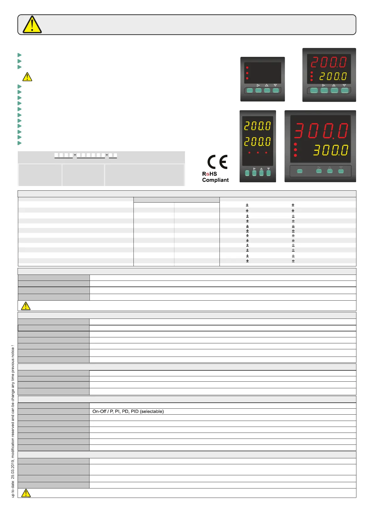
ENDA ET SERIES PID TEMPERATURE CONTROLLER
Thank you for choosing temperature controller.ENDA ET SERIES PID
Input Type
J (Fe-CuNi) Thermocouple
(Fe-CuNi)L Thermocouple
J (Fe-CuNi) Thermocouple
(Fe-CuNi)L Thermocouple
K (NiCr-Ni) Thermocouple
K (NiCr-Ni) Thermocouple
T (Cu-CuNi) Thermocouple
T (Cu-CuNi) Thermocouple
S (Pt 0Rh-Pt)1 Thermocouple
R (Pt13Rh-Pt) Thermocouple
EN 60584
DIN 43710
EN 60584
DIN 43710
EN 60584
EN 60584
EN 60584
EN 60584
EN 60584
EN 60584
Accuracy
0, % ( )5 of full scale
0, % ( )5 of full scale
0, % ( )5 of full scale
0, % ( )5 of full scale
0, % ( )5 of full scale
0, % ( )5 of full scale
1 digit
1 digit
1 digit
1 digit
1 digit
1 digit
0, % ( )5 of full scale
0, % ( )5 of full scale
1 digit
1 digit
0, % ( )5 of full scale 1 digit
0, % ( )5 of full scale 1 digit
PT100 Resistance thermometer
PT100 Resistance thermometer
EN 60751
EN 60751
0,2% ( )of full scale
1 digit
0,2% ( )of full scale 1 digit
Temperature Range
°C
°F
- 99.9... 00.01 6
-30.0....600.0°C
-30.0....600.0°C
-30.0...999.9°C
-30.0...400.0°C
-200...600
-30....600°C
-30....600°C
-30...1300°C
-30....400°C
-40...1700°C
-40...1700°C
°C
°C
...-22.0 .999.9 °F
...-22.0 .999.9 °F
...-22.0 .999.9 °F
. 752-22.0 ... .0 °F
- 99.9... .1 999 9
... 2 2-22 . 37 °F
... 752-22 ...
...-40 .3092
...-40 .3092
-328... 112.1
... 1112-22 . °F
... 1112-22 . °F
°F
°F
°F
°F
°F
110V AC +%10 -%20, 230V AC +%10 -%20, 50/60Hz 24V AC %10, 50/60Hzor ±
Max. 5VA
Power : , Si : 1 ²connector 2.5mm²' screw-terminal gnal connector ,5mm screw-terminal conenction.
EEPROM ( )minimum 10 years
Max. 100ohm
1 bit2
00ms1
Relay : 250V AC, (resistive load), Selectable as NO+NC Control or Alarm2 output.8A
C/A2 output
SSR output
Max 20mA 24Volt
OUTPUTS
Life expectancy for relay
ELECTRICAL CHARACTERISTICS
Supply
Power consumption
Wiring
Line resistance
Data retention
EMC
Safety requirements
EN 61326-1: 2013
EN 61010-1: 2010 (Pollution degree 2, overvoltage category II)
CONTROL
Control type
Single set-point and alarm control
Control algorithm
A/D converter
Sampling time
Proportional band
Control period
Adjustable between 0 and 100 . If Pb=0.0 , On-Off control is selected.% % %
and 125 secondsAdjustable between 1
Relay : 250V AC, (resistive load), NO (Selectable as Alarm1 or Cooling Control output).8A
Mechanical 30. Mio; Electrical 100.000 operation. 250V AC, 8A (resistive load).
ENVIRONMENTAL CONDITIONS
Height
Max. 2000m
Ambient/storage temperature
Max. Relative humidity
0 ... +50 /°C -25... +70°C (with no icing)
Rated pollution degree
According to EN 60529 Front panel : IP65, Rear panel : IP20
Do not use the device in locations subject to corrosive and flammable gases.
Relative humidity 80% for temperatures up to 31°C decreasing linearly to 50% relative humidity at 40°C.
A1 output
Hysteresis
Output power
1 and 50Adjustable between °C/F
The ratio of power at a set point can be adjusted between 0 and 100% %
HOUSING
Housing type
Suitable for flush-panel mounting according to DIN 43 700.
Dimensions
ET4420 : G48XY48XD87MM ET7420 : G72XY72XD97MM
ET8420 : G48XY96XD87MM ET9420 : G96XY96XD50MM
Weight
Approx. 400g after packing (250g for ET4420).
Self extinguishing plastics.
Enclosure material
While cleaning the device, solvents (thinner, , acid etc.) or must not be used.gasoline corrosive materials
Selectable dual setpoint.
Selectable thermocouple types.
Automatic calculation of PID parameters (SELFTUNE).
Selftune for automatic PID calculation or
manually enter PID parameters if known.
Three different specifications can be assigned to digital input.
Three different specifications can be assigned to F function key.
Soft-Start feature.
Selectable SSR control output.
C/A2 Relay output programmable as secondary alarm or control output.
A1 Relay output programmable as primary alarm or PID cooling output.
Selectable heating/cooling control.
Zero point input shift.
In case of sensor failure, manually, periodical or auto-periodical control can be selected.
RS485 ModBus protocol communication feature (optional).
CE marked according to European Norms.
A1
C/A2
SSR
TEMPERATURE CONTROLLER
ET 9420
ENDA
PV
SV
SET
F
C/A SET
ET 8420
ENDA
TEMPERATURE CONTROLLER
SET
C/A SET
F
C/A2
SSR
A1
PV
SV
TEMPERATURE CONTROLLER
ENDA
ET 7420
C/A2
SSR
A1
PV
SV
F
C/A SET
SET
TEMPERATURE CONTROLLER
ENDA
C/A SET
F
SET
E 442T 0
C/A2
A1
SSR
PV
SV
1200
1200
Order Code : ET
1
1 - Size
4420.....48x48x87mm
7420.....72x72x97mm
8420.....48x96x87mm
9420.....96x96x50mm
2 -
230VAC...230V AC
24VAC.....24V AC
SM...........9-30V DC /
7-24V AC
Supply Voltage
3 -
RS..... RS-485
....
...
( )
Blank
Modbus (Optional)
Modbus Available
Optional / Specify at order
N/A
2
0
2 3
4
Read this document carefully before using this device. The guarantee will be expired by device demages if you don't attend to the directions in
the user manual. Also we don't accept any compensations for personal injury, material damage or capital disadvantages.
E-mail : info@suran-elektronik.de
Internet : www.suran-elektronik.de
Tel.: +49 (0)7451 / 625 617
Fax: +49 (0)7451 / 625 0650
SURAN Industrieelektronik
/ D-72160 Horb a.NDettinger Str. 9
english
C.E.c,t.
C.E.c.t. E..P.S.
C.E.P.S.
C.E.c.t Auto.
= Faulty sensor control type.
If , in the case of probe
failure according to proportional
value of the parameter control is performed.
If in the case of probe
failure, the fault found and recorded before
the last setpoint control with the control
percentage is performed.
=
=
SET
C SET/A
C SET/A
SET
F
F
F
SET
C SET/A
F
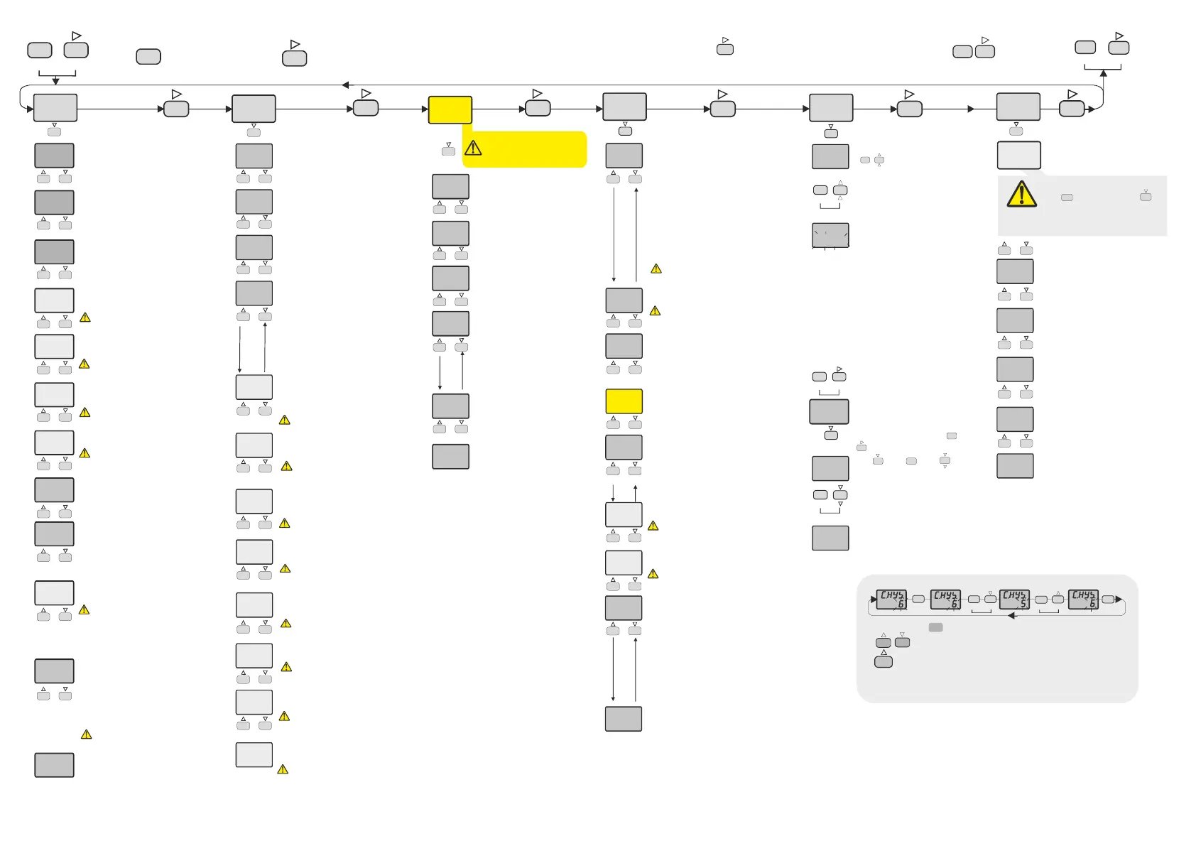
Entering from the "Programming Mode" to the "Running Mode" :
If no key is pressed within 20 seconds during "Programming Mode", the data is stored automatically and the "Running Mode" is entered.
Alternatively, the same function occurs first pressing key is pressing "Programming Mode" is entered. Then keys
are pressing together, data is recorded and "Running mode" is entered.
F
F
F
F
F
F
F
SET
C SET/A
F
C.s.Lo.
0
C.s.Hi.
600
C. pb
4.0
C. ti
4.0
C. td
1.00
C.p.st
0
C.Hys
2
C. Ct.
1
s.s.t.s.
0
C.E.p.s.
0
C.E.C.t.
E.PS.
Con.o.
Co.sc.
p.yEs
a.1..sc.
p.yEs
a.2.sc.
p.yEs
Cn.sC.
p.yEs
S.t.sc.
p.yEs
inp.t.
J
Unit
°C
fltr.
5
C.o.sE
C-A2
offs.
0
d.Adr.
1
baud
9.60
d.in.C.
nonE
F.kE.C.
off
A1.S.L
0
A1.S.H
600
A1.HY
2
A1.tP.
INDE.
A1.St.
hi.
A1.Er.
ON
A1.PB
0
A1.ti
0
A1.td
0
A1.Ct
1
A1.ps
0
A1.Ep
0
A2.S.L
0
A2.S.H
600
A2.HY
2
A2.tP
INDE.
A2.St.
hi.
A2.Er.
ON
S.Cod.
0
s.t.us.
SET
CSET
Pid.t.
25
s.tun.
s.t.us.
SET
SET
CSET
CSET
400
25
Al1.o.
Al2.o.
Conf.. s.tun. SECU.
STOPPING SELF TUNE
If key is pressed while holding key, the "Programming Mode" is enabled.
C.s.lo.= C / A2 Output Control setpoint
value lower limit.
Adjustable between 0 and C.s.Hi.
C.s.Hi.= C / A2 Output Control setpoint
value upper limit.
Adjustable between and Upper
scale value.
C.s.Lo.
C. Pb
C. Pb
= C / A2 Output P
%0 %100
= %0 On-Off
roportional band
value.
Adjustable between .0 and .0.
If .0, control is selected.
C.Hys
C. Pb
= C / A2 Output Hysteresis output
value.
Adjustable between 1 and 50 °C.
If = 0, this parameter is active.
C. ti
C. ti
C. Pb
= C / A2 Output value
=
If
Integral .
Adjustable between 0 and 100.0 minutes.
0.0,integral impact is disable.
parameter is different from
“0”, this parameter appears.
C. td
C. td
C. Pb
= C / A2 Output value
=
Derivative .
Asjustable between 0.00 and 25.00 minutes.
0.0, derivative time is disabled.
If parameter is different from”0”,
this parameter appears.
C. Ct.
C. Pb
= C / A2 Output Period time.
Adjustable between 1 and 250 second.
parameter is different is different
from“0”, this parameter appears.
C.E.P.s.
C.E.c.t E.PS. C. Pb 0.0
C. Pb 0.0
C.E.P.S 0
= In the case of probe failure, C / A2
output adjustable between
= or = is
selected, this parameter is activated.
In the case of failure, if = (ON/Off
Control) and = output will be Off,
if different from “0” value, output will be ON.
percentage %0
and %100.
If
S.S.t.S. = Soft Start timer set value.
This parameter indicates the time to
reach set point value when the device is
first ene gised.r
Adjustable between 0 and 250 minutes.
If 0 is selected, soft start feature will be
enable and the device reaches set point
value quickly.
Pb = 0, so start feature will
be disable .
Setting ft
d
C.p.st =
and
At C / A2 Set value, C/A1 percent of
power.
Adjustable between 0% 100%.
a1.s.l= Alarm1 set value lower limit.
parameter value.
Adjustable between and0 A1.S.H
a1.s.H= Alarm1 set value upper limit.
Adjustable between parameter value
and upper scale value.
A1.S,L
a1.Hy= Hysteresis of the Alarm1 output.
Adjustable between 1 and 50 C.°
A1.tp
indE.
dE.
bAnd
bAn.i
= Alarm1
= Independent
= alarm
= Band alarm (Band)
=
Type of .
Six kinds of functions can be selected.
alarm
Deviation
Band with inhibition
in.Co.
rE.Co
= A1 output independent cooling
control
= A1 output relative cooling control
A1.st.
Hi
= Alarm1 output situation.
If Alarm1 output outputis above
the Alarm1 set value ; on.
= A1
lo
A1.tP. in.Co. rE.Co.
= A1
para
output is above the Alarm1 set
value ; off.
meter , or is
selected; this parameter is not seen.
A1.Er.
on
= Alarm
output probe failure; on.
1 probe failure situation.
= A1
off
A1.tP. in.Co. rE.Co.
= A1 output probe failure; off.
parameter, or is
selected, this parameter is not seen.
A1.Pb
A1.Pb
A1.tP. in.Co. rE.Co.
=
0 and
= 0 , On-Off control is selected.
A1 output,value of proportional
band.
Adjustable between % 100%.
%
parameter, or is
selected,this parameter is activated.
A1.ti
A1.ti
A1.tp. in.Co. rE.Co.
A1.Pb
=
=
and if different from “0” ,
A1 output integral value.
Adjustable between 0.0 and 100.0 minute.
0.0 effect of integral disable.
parameter, or is
selected
this parameter is activated.
A1.td
A1.td
A1.tp. in.Co. rE.Co.
A1.Pb
=
= .
and if different from “0”,
this parameter is activated.
A1 output derivative value.
Adjustable between 0.00 and 25.00 minute.
0.00 effect of derivative disable
parameter or is
selected
A1.Ct
A1.tp. in.Co. rE.Co.
A1.Pb
=
and if different from “0”,
this parameter is activated.
A1 output period time.
Adjustable between 1 and 250sec.
parameter or is
selected
A1.Ps
A1.tp. in.Co. rE.Co.
A1.Pb
=
and
and if different from “0”,
this parameter is activated.
At A1 Set value, A1 output percent
of power.
Adjustable between 0% 100%.
parameter or is
selected
A1.Ep
A1.tp. in.Co. rE.Co.
= At A1 Set value, A1 output percent
of power.
Adjustable between 0%-100%.
parameter or is
selected, this parameter is activated.
In SSR output devices, if
parameter is different
from , this menu
appears.
co.SE
C-A2
a2.s.l= Alarm
parameter value.
2 set value lower limit.
Adjustable between and0 A2.S.H
a2.s.H= Alarm2 set value upper limit.
Adjustable between parameter
value and upper scale value.
A2.S,L
a2.Hy= Hysteresis of the Alarm2
output.
Adjustable between 1 and 50 C.°
A2.tp
indE.
dE.
bAnd
bAn.i
=
= Independent
= Deviation
= Band alarm
=
Type of Alarm2.
Four kinds of functions can be
selected.
alarm
alarm
Band with inhibition
A2.st.
Hi
= Alarm2
2 output is above the set
value;on
output situation.
= A
lo= A2 output is above the set value;
off.
A2.Er.
on
= Alarm
2 output probe failure; .
2 probe failure
situation.
= A on
off= A2 output probe failure;off.
inp.t.
Pt.0
Pt.
J.0
j
k.0
k
L.0
L
t.0
t
s
r
= Type of input selection.
= PT100 decimal,
= PT100 Non-decimal,
= J Type decimal,
= J Type Non-decimal,
= K Type decimal,
= K Type Non-decimal,
= L Type decimal,
= L Type Non-decimal,
= T Type decimal,
= T Type,
= S Type,
= R Type, thermocouple selection.
This parameter varies when changing
some parameters.
Unit = The temperature unit.
= °C, = °F
This parameter varies when changing
some parameters.
°C °F
fLtr. = Coefficient of digital filter.
Adjustable between 1 and 200.
If this parameter is 1, digital filter runs most
quick. If the parameter is 35, the filter run
most slow. The value of parameter should be
increased in interference.
C.o.sE = Control output selection
C-A2
SSR
= C/A2 (Relay) output selection
= SSR output selection
oFFS. = Offset
-99 99°C, for decimal
values can be adjusted between -10.0 and 10°C.
Normal
value.
Offset value is added to the measuring value.
This feature which is the point of measurement
due to its distance measurement probe, is used
to eliminate errors that might occur.
Adjustable between and
value=0.
D.aDr. = Device address for RS485 connection.
Adjustable between and .
This parameter is active devices with
RS485 communications option.
1 247
baud = ModBus baud rate for RS485 connection
Selectable as; off, 2.4, 4.8, 9.6, 19.20 ve 38.40 .
This parameter is active devices with RS485
communications option.
d.in.C. = Digital input setting parameter.
nonE
C2.S.A.
manu.
C.Ct
m.SEt
dSP.o.
= Digital input is closed.
= if digital input is activated, 2nd set value
is used.
=
= If the digital input is activated;
temperature indicator mode can be exceed.
Manual mode start in case of digital
outputs are active and and rational output
generated according to period value in
paremeter and percentage value in
parameter.
F.kE.C. = Function key setting parameter.
nonE
C2.S.A .
manu.
dSP.o.
= Function key is closed.
= The function key is used with the 2nd set value.
= Manual mode can be exceed by using the
function key.
= Temperature indicator mode can be exceed by
using function key.
S.Cod = Security menu access
code.
It should be 442.
If in = position, first held
down key then pressed
key for 4 seconds message
is displayed and return to the
factory settings.
S.Cod 0
dEfP
SET
Cosc. CoN.o.
nonE
P.yEs
P. no
=
=
=
Parameter of menu
security level.
Menu invisible.
Modification can be done.
= Only visible.
a.1.sc. al1..o.
nonE
P.yEs
P. no
=
men
= .
=
Parameter of
u security level.
Menu invisible
Modification can be done.
= Only visible.
a.2.sc. al2..o.
nonE
P.yEs
P. no
=
=
=
Parameter of
menu security level.
Menu invisible.
Modification can be done.
= Only visible.
Cn.SC. ConF .
nonE
P.yEs
P. no
=
=
=
Parameter of
menu security level.
Menu invisible.
Modification can be done.
= Only visible.
S.t.Sc.. S.tun...
nonE
P.yEs
=
=
=
Parameter of
menu security level.
Invisible.
Modification can be done.
s.t.us.
pid.t.
tE.hi.
P id . t.
C.Pb C t C. dt C. Ct.
S.tun.
s.t.sc.
p.yEs SECU
= Self tune control parameter.
If keys are pressed together, the
device returns to the main screen and if
the temperature is not high,
message flashes on display and self tune
process starts automatically. If the initial
temperature is higher to self-tune,
message appears and the device waits
until the temperature goes down. Then
m e s s a g e a p pear s a n d
automatically self tune procedure is
starts. After the self tune procedure,
, , and values ??are
recorded in the memory, then the device
returns to "Running mode". After the
successful self tune completion,
menu is removed automatically. In order
to re-tune, parameter should be
set to in menu.
SET
CSET
If self tune process wanted to be
terminated for any reason ,
"Programming Mode" entered and
menu opened with and
keys, parameter selected
with key, and keys
pressed together in order to stop self
tune process and turn to main
display.
S.tun
S.t.uS
SET
CSET
SET
CSET
SET
SET
Parameter Setting Diagram
SET
SET
C SET/A
C SET/A C SET/A C SET/A
SET
C SET/A
When holding key, the value of parameter flashes and using
keys the requested value can be adjusted.
If key is pressed and held 0.6 seconds, the value of the selected
parameter changes rapidly. If waited enough,the value increases 100 at each
step. After 1 second following the release of the key, initial condition is
returned.The same procedure is valid for the decrement key.
C.typ
HEAt
C.typ. = Control output type
C.typ. HEAt
C.typ. CooL
=
=
means heating control.
means cooling control.
ETx420-E-25032019
2. / 4
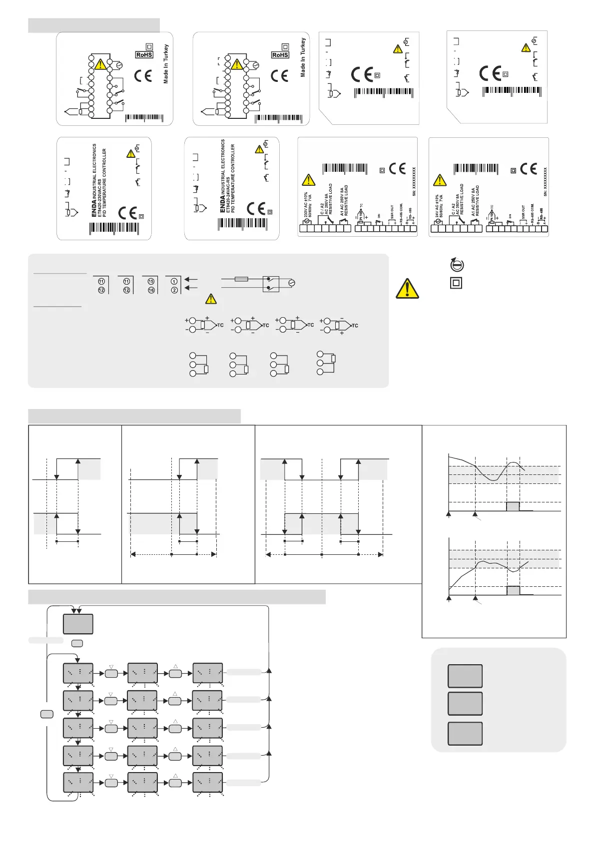
CONNECTION DIAGRAM
Logic output of the instrument is not electrically
insulated from the internal circuits. Therefore, when
using a grounding thermocouple, do not connect the
logic output terminals to the ground.
1)
2)
Mains supply cords shall meet the requirements of
IEC 60227 or IEC 60245.
In accordance with the safety regulations, the power
supply switch shall bring the identification of the
relevant instrument and it should be easily accessible
by the operator.
Note :
Holding screw
0.4-0.5Nm
Equipment is protected throughout
by DOUBLE INSULATION.
ALARM1 AND ALARM2 OUTPUT TYPES
Independent Alarm
A1.tp. indE=
Deviation Alarm
= A1.tp dE.
Band
=
Alarm
A1.tp. bAnd
A1.St. Hi=
A1.St. lo=
=A1.St. Lo
=A1.St. Hi
ASV
SV
SV
SV
SV+ASV
SV+ASV
SV-ASV
OFF
OFF
OFF
OFF
OFF
OFF
-300
300
+300
300
ON
ON
ON
ON
ON
ON
SV = CONT output set value ASV = Alarm output set value
(ASV min. =-300, ASV maks. = +300)
(ASV min. = 0, ASV ma . = +300)x
(ASV min. = beginning of scale
ASV max. = end of scale)
SV =CONT set ASV = AL1 setoutput value output value
a1,Hy
A1.Hy
A1.Hy
A1.Hy
=
Band Alarm With Inhibition
A1,tp. bAn.i
ON
ON
OFF
OFF
Beginning
SV =
ASV =
(ASV min. = 0, ASV ma = 300 )
Set point of CONT output
Set point of AL1 output
x.
Band alarm is possible
Band alarm is possible
Beginning
SV
SV
SV+ASV
SV+ASV
SV-ASV
SV-ASV
SET
C SET/A
250
400
C1.SE.
400
C2.SE.
400
a1.SE.
500
a2.SE.
500
m.SEt
50
C1.SE.
400
C2.SE.
400
a1.SE.
500
a2.SE.
500
m.SEt
50
C1.SE.
399
C2.SE.
399
a1.SE.
499
a2SE.
499
m.SEt
49
SET
C SET/A
SETTING UP ALARM CONTROL AND SETPOINT VALUES
3 seconds later
3 seconds later
3 seconds later
3 seconds later
3 seconds later
3 seconds later
If the parameter is set to SSR out,
this parameter is seen.
C.O.SE.
If one of the or parameters are
set to the value, this parameter is seen.
d.in.c. f.kE.c.
C2.S.A.
If one of the or parameters are
set to the value and if is different
from 0, this parameter is seen.
d.in.c. f.kE.c.
mAnu. C. Pb
ERROR MESSAGES
pfa
400
400
____
400
----
Temperature sensor
is broken.
Temperature value is
higher than the scale.
Temperature value is
broken or over temperature.
ENDA
INDUSTRIAL ELECTRONICS
E - VAC
PID CONTROLLER
T7420 230 - RS
TEMPERATURE
V AC +10% -20%
50/60Hz 7VA
230
C / A2
AC 250V
RESISTIVE
LOAD
8A
A1
AC 250V
RESISTIVE
LOAD
8A
11
12
13
14
15
16
17
SN: XXXXXXXXX
8 680407 705955
Made in Turkey
-
+
RS-485
COM.
RS- 485
SSR
OUT
A
B
+
-
TC
+
-
Pt 100
9
8
5
4
3
2
1
10
7
6
DIN
ENDA
INDUSTRIAL ELECTRONICS
E - VAC
PID CONTROLLER
T7420 24 - RS
TEMPERATURE
V AC +10% -20%
50/60Hz 7VA
24
C / A2
AC 250V
RESISTIVE
LOAD
8A
A1
AC 250V
RESISTIVE
LOAD
8A
11
12
13
14
15
16
17
SN: XXXXXXXXX
8 680407 705955
Made in Turkey
-
+
RS-485
COM.
RS- 485
SSR
OUT
A
B
+
-
TC
+
-
Pt 100
9
8
5
4
3
2
1
10
7
6
DIN
1
8
2
9
7
16 17
6
15
3
10
4
13
5
14
ENDA
INDUSTRIAL ELECTRONICS
ET9420-2 VAC-RS
PID CONTROLLER
30
TEMPERATURE
-
8 6804 07 70 6129
Made in Turkey
11
12
1
8
2
9
7
16 17
6
15
3
10
4
13
5
14
-
11
12
1
8
2
9
7
16 17
6
15
3
10
4
13
5
14
ENDA
INDUSTRIAL ELECTRONICS
ET9420-2 VAC-RS
PID CONTROLLER
4
TEMPERATURE
-
8 6804 07 70 6129
Made in Turkey
11
12
1
8
2
9
7
16 17
6
15
3
10
4
13
5
14
-
11
12
-
+
RS-485
COM.
RS- 485
SSR
OUT
A
B
+
-
SN: XXXXXXXXX
15
16
17
18
19
20
21
2 V AC +10% -20%
50/60Hz 7VA
4
C / A2
AC 250V
RESISTIVE
LOAD
8A
A1
AC 250V
RESISTIVE
LOAD
8A
TC
+
-
Pt 100
11
10
7
6
5
4
3
12
8 680407 706044
Made in Turkey
9
8
DIN
-
+
RS-485
COM.
RS- 485
SSR
OUT
A
B
+
-
SN: XXXXXXXXX
15
16
17
18
19
20
21
2 V AC +10% -20%
50/60Hz 7VA
30
C / A2
AC 250V
RESISTIVE
LOAD
8A
A1
AC 250V
RESISTIVE
LOAD
8A
TC
+
-
Pt 100
11
10
7
6
5
4
3
12
8 680407 706044
Made in Turkey
9
8
DIN
DIN
9
10
6
8
ET4420
ET7420
ET8420
ET4420
ET7420
ET8420
ET9420
ET4420 ET7420
ET8420 ET9420
9
10
9
10
12
11
11
12
10
9
10
8
ET9420
8
9
9
10
8
NOTE :
SUPPLY VOLTAGE
F 100 mA
250V AC
230V AC 24V ACor
Supply
Cable Size : 1,5mm²
Line
Neutral
Fuse should
be connected.
Switch
184-253V AC
50/60Hz 7VA
SENSOR INPUT:
For J - K - T- S and R Thermocouples :
Use the correct compensating cable.
Do not make any supplement to cables. Connect
the thermocouple cables to the right places at the
input terminal.
PT100
PT100
PT100
PT100
For PT100 Sensorresistance ( ) :
When using 2-wire PT100 sensor, as shown in the
figures, make 8 and 9 terminals short circuit for
ET4420, ET7420 and ET9420 devices, make 10 and 11
terminals short circuit for ET8420 devices.
ETx420-E-25032019
3. / 4
SN: XXXXXXXXX
INDUSTRIAL ELECTRONICS
ET44 0-
P TEMPERATURE CONTROLLER
2 230V
ID
ENDA
8 680407 715497
C/A2
A1
AC 250V
RESISTIVE LOAD
8A
AC 250V
RESISTIVE LOAD
8A
SSR OUT
DIN
16
8
17
9
10
11
1
12
2
13
3
14
4
15
5
6
7
+
-
2 V AC ±10%
50/60Hz 5VA
30
-
+
TC
PT100
SN: XXXXXXXXX
INDUSTRIAL ELECTRONICS
ET44 -
P TEMPERATURE CONTROLLER
20 230V-RS
ID
ENDA
8 680407 715510
C/A2
A1
AC 250V
RESISTIVE LOAD
8A
AC 250V
RESISTIVE LOAD
8A
SSR OUT
DIN
16
8
17
9
10
11
1
12
2
13
3
14
4
15
5
6
7
+
-
2 V AC ±10%
50/60Hz 5VA
30
-
+
TC
PT100
-
+
RS- 485
A
B
RS-485 COM.
Product Specifications
| Brand: | Enda |
| Category: | Thermostat |
| Model: | ET4420 |
Do you need help?
If you need help with Enda ET4420, ask a question below and other users will answer you
Thermostat Enda User Manuals

16 October 2024
15 October 2024
15 October 2024
15 October 2024
15 October 2024
15 October 2024
Thermostat User Manuals
- Thermostat ATAG
- Thermostat Bosch
- Thermostat AEG
- Thermostat Siemens
- Thermostat EBERLE
- Thermostat Schwaiger
- Thermostat Oreg
- Thermostat Netatmo
- Thermostat Busch-Jaeger
- Thermostat Danfoss
- Thermostat Schneider
- Thermostat EMOS
- Thermostat Heatit
- Thermostat Dimplex
- Thermostat Velleman
- Thermostat GE
- Thermostat Tru Components
- Thermostat Bearware
- Thermostat Max
- Thermostat Elgato
- Thermostat EVE
- Thermostat ORNO
- Thermostat Avidsen
- Thermostat STI
- Thermostat Hunter
- Thermostat Basetech
- Thermostat TFA
- Thermostat REMKO
- Thermostat Vaillant
- Thermostat Boneco
- Thermostat Grohe
- Thermostat Drayton
- Thermostat Jung
- Thermostat Ambiano
- Thermostat Crestron
- Thermostat Xavax
- Thermostat Remeha
- Thermostat Heatmiser
- Thermostat Hive
- Thermostat GENERAL Life
- Thermostat Silvercrest
- Thermostat HomePilot
- Thermostat Elektrobock
- Thermostat Corberó
- Thermostat Delta Dore
- Thermostat Homematic IP
- Thermostat Vimar
- Thermostat Emerson
- Thermostat Salus
- Thermostat Fenix
- Thermostat Baxi
- Thermostat Honeywell
- Thermostat Google
- Thermostat Emko
- Thermostat Wachendorff
- Thermostat Elro
- Thermostat De Dietrich
- Thermostat Theben
- Thermostat Computherm
- Thermostat Vemer
- Thermostat Grasslin
- Thermostat Niko
- Thermostat H-Tronic
- Thermostat Gira
- Thermostat Fantini Cosmi
- Thermostat Radson
- Thermostat Junkers
- Thermostat Buderus
- Thermostat Viessmann
- Thermostat Tado
- Thermostat Amfra
- Thermostat Aube
- Thermostat Eneco
- Thermostat Orbis
- Thermostat Emmeti
- Thermostat Optima
- Thermostat Drayton Erie
- Thermostat Carrier
- Thermostat Eurotronic
- Thermostat PECO
- Thermostat Intertechno
- Thermostat Maico
- Thermostat Frico
- Thermostat Bulex
- Thermostat Gewiss
- Thermostat Etherma
- Thermostat Horstmann
- Thermostat Plugwise
- Thermostat Mikoterm
- Thermostat Cepra
- Thermostat ChiliTec
- Thermostat King
- Thermostat Sygonix
- Thermostat Landis Gyr
- Thermostat Saunier Duval
- Thermostat Itho-Daalderop
- Thermostat Finder
- Thermostat ICY
- Thermostat THERMAFLEX
- Thermostat Rose LM
- Thermostat Seitron
- Thermostat IMIT
- Thermostat Watts
- Thermostat Nefit
- Thermostat Econo-Heat
- Thermostat EQ3
- Thermostat Ferroli
- Thermostat Hager
- Thermostat Otio
- Thermostat Jumo
- Thermostat EQ-3
- Thermostat Magnum
- Thermostat Webasto
- Thermostat UPM
- Thermostat Eqiva
- Thermostat Johnson Control
- Thermostat Devi
- Thermostat Tylö
- Thermostat AWB
- Thermostat ELKO
- Thermostat Yokis
- Thermostat Technoline
- Thermostat 2Heat
- Thermostat RWE
- Thermostat ACV
- Thermostat Plieger
- Thermostat Veria
- Thermostat Wallair
- Thermostat Stiebel Eltron
- Thermostat Trotec
- Thermostat Hugo Muller
- Thermostat VDH
- Thermostat Ouellet
- Thermostat Nest
- Thermostat Innogy
- Thermostat Devolo
- Thermostat Zehnder
- Thermostat Go Green
- Thermostat EasyTemp
- Thermostat Levica
- Thermostat Coati
- Thermostat Berker
- Thermostat MundoControl
Latest Thermostat User Manuals
25 October 2024
25 October 2024
25 October 2024
25 October 2024
25 October 2024
25 October 2024
25 October 2024
25 October 2024
25 October 2024
25 October 2024